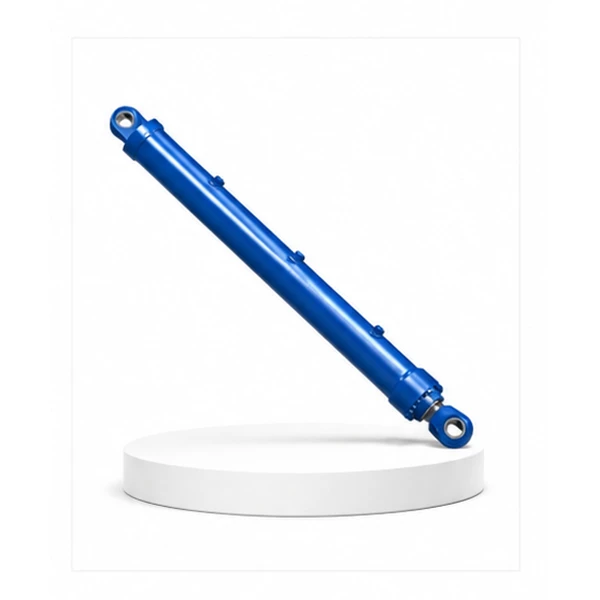
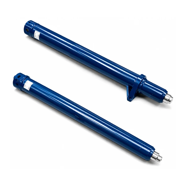
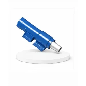
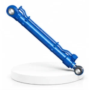
Rotary Drilling Mast Cylinder

Mast Cylinder vs Luffing Cylinder — Two Cylinders, Two Kinds of Angle Control
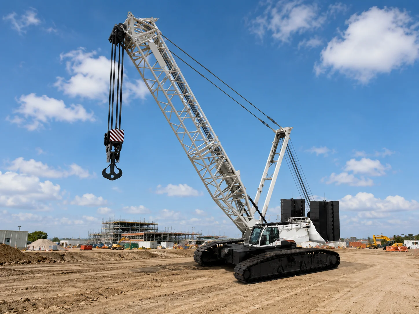
The luffing cylinder (#24) erects the mast from transport-horizontal to working-vertical — a large-angle, high-force motion performed once per setup. The mast cylinder operates after the mast is erected: it fine-adjusts the mast angle in the fore/aft plane and — on some rig designs — provides the structural bracing that holds the mast rigid against the lateral forces generated during drilling.
The mast cylinder connects the top (or mid-height) of the mast to the rig's chassis through a linkage. By extending or retracting, it tilts the mast forward or backward by small amounts — typically ±5° from the vertical set by the luffing cylinder. This fine-tilt capability allows the operator to compensate for ground slope, chassis settling, and borehole position offsets without re-levelling the entire machine.
The 5,550 mm stroke is driven by the mast height — the cylinder's connection point is high on the mast (for maximum leverage), and the long stroke accommodates the full range of mast-to-chassis distance as the mast tilts through its adjustment range. Korea Ever-Power manufactures the mast cylinder as the second of three rotary drilling rig cylinders.
Technical Specifications
| Parameter | Specification |
|---|---|
| Product | Rotary Drilling Mast Cylinder |
| Function | Control the mast — adjust angle between mast and ground |
| Bore Diameter | 140 mm – 350 mm |
| Rod Diameter | 90 mm – 230 mm |
| Stroke | ≤ 5,550 mm |
| Working Pressure | Up to 32 MPa |
| Application | Rotary Drilling Rig |
| Certification | ISO 9001 · 100% hydrostatic tested |
The Mast Cylinder as a Structural Brace — Absorbing Drilling Reaction Forces
During drilling, three reaction forces try to move the mast out of position. The mast cylinder resists all three simultaneously:
The rotary table applies 200–500 KNm of torque to the drill string. The equal-and-opposite torque reaction tries to twist the mast around its vertical axis. The mast cylinder, connected at an offset from the mast centreline, provides a restoring moment that opposes this twist — keeping the mast from rotating as the drill turns.
The pressurised cylinder (#26) pushes the power head downward with 100–300 KN of force to penetrate hard ground. This downward force, acting at the top of the mast, creates a forward-tilting moment on the mast base. The mast cylinder pushes back, preventing the mast from leaning forward under the drilling crowd force.
A 25-metre mast presents a large sail area to the wind. At working wind speeds (up to 15 m/s), the lateral wind force on the mast can reach 10–30 KN. The mast cylinder's counterbalance valve and the oil column's stiffness provide damping that prevents the mast from oscillating in gusty conditions. Contact the Korea Ever-Power engineering team for mast cylinder force calculations.
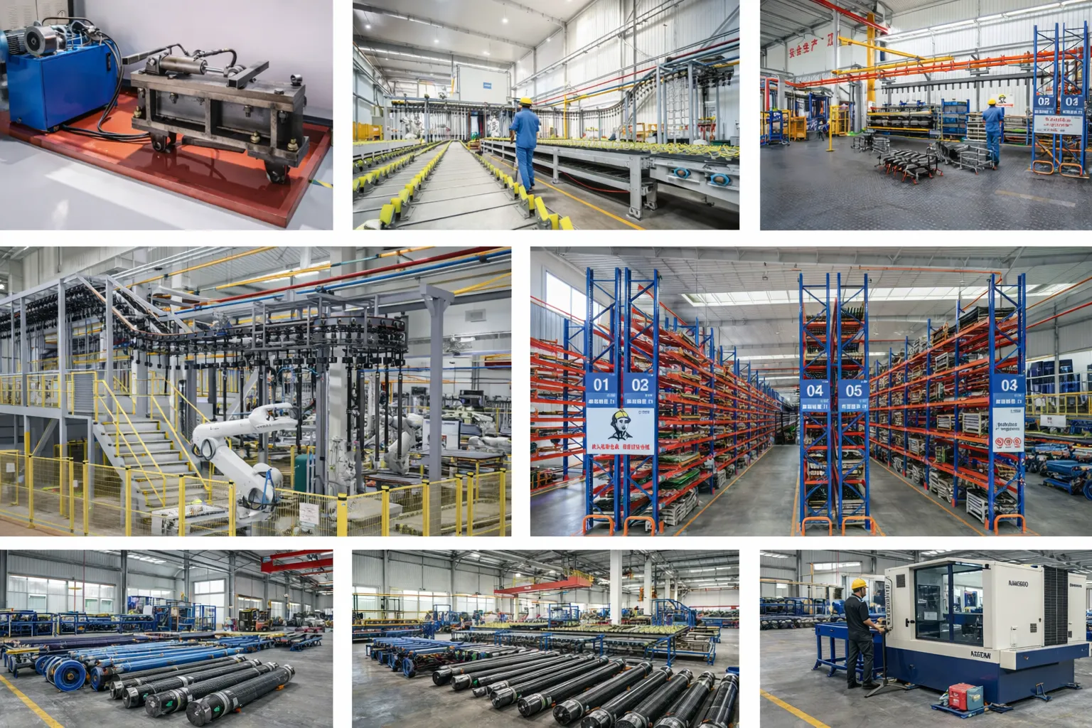
Manufacturing Process
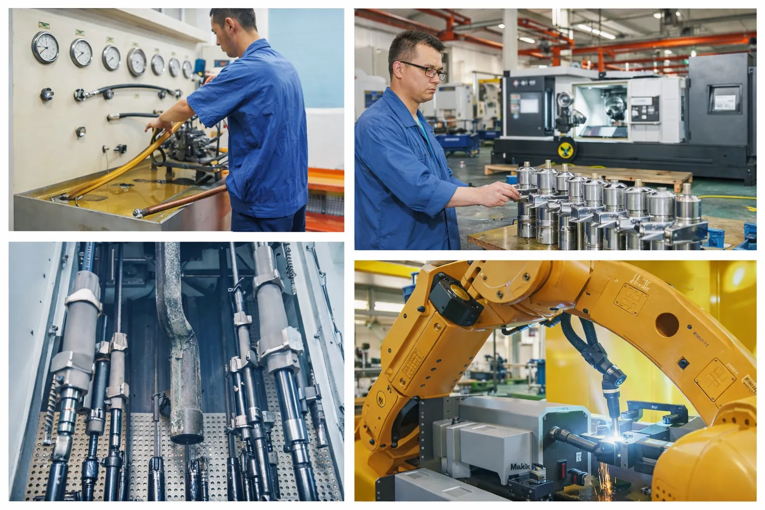
The mast cylinder combines long stroke (5,550 mm) with a substantial bore (140–350 mm) — creating a large, heavy cylinder that must be manufactured with the same rod-straightness and concentricity standards as the crane luffing cylinder. Rod straightness ≤0.1 mm/metre across the full 5.5-metre extended length. Euler buckling is verified at full extension under the combined axial and lateral loading from drilling reaction forces.
Bore finish Ra 0.2–0.4 µm. Chrome plating 50–80 µm (construction site environment — bentonite slurry, drilling mud, and cement splash are the primary contaminants). The rod eye uses a spherical bearing to accommodate the changing angle between the cylinder and the mast as the mast tilts. Seals are polyurethane + NBR wipers rated for -30 °C to +80 °C.
Every mast cylinder is hydrostatic tested at 1.5× rated pressure and load-holding tested with a counterbalance valve — verifying zero drift under simulated drilling reaction forces over a defined hold period.
OEM & ODM
FAQ
Related Categories
Additional information
| Editor |
|---|
Related products
-
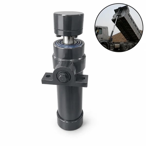
Mining Dump Truck Front Suspension Cylinder
-
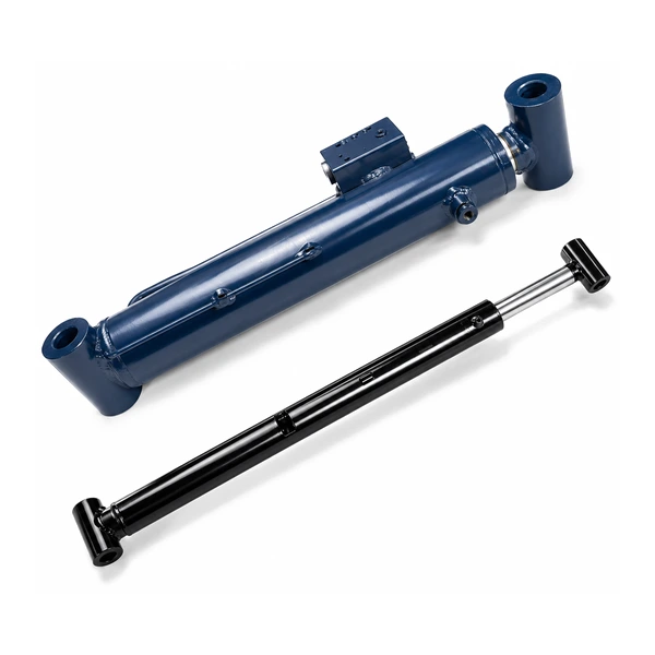
Rotary Drilling Luffing Cylinder
-
Mobile Crane Counterweight Cylinder
-
Mining Dump Truck Steering Cylinder
-
Large Excavator Stick Cylinder (Arm Cylinder)
-
Small Excavator Stick Cylinder (Arm Cylinder)
-
Mobile Crane Luffing Cylinder
-
Mobile Crane Suspension Cylinder


