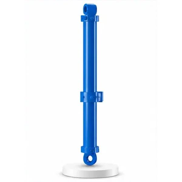
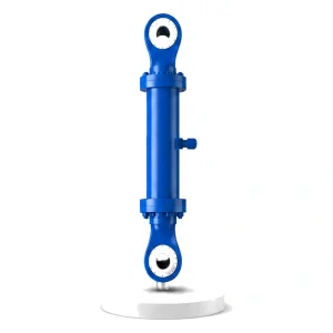
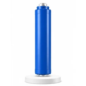
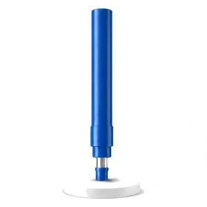
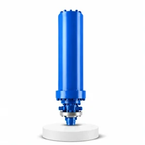
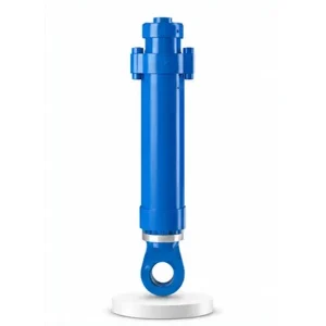
Hydraulic Press Lateral Shift Anvil Cylinder

The Only Cylinder
That Moves Sideways
Master, side, return, leveling, tilt — every other cylinder on a hydraulic press acts vertically or angularly. The lateral shift anvil cylinder acts horizontally. It slides the entire anvil and lower die assembly across the press bed — positioning different die stations under the ram or shifting the workpiece laterally between forging passes.
Why Move the Anvil Sideways?
On a free-forging press, the workpiece goes through multiple forming steps — upsetting, drawing-out, flattening, punching — each requiring a different die shape. Without lateral shift, the operator must stop the press, crane-lift the old die out, crane-lift the new die in, align it, and clamp it. This changeover takes 15–60 minutes per die swap and breaks the forging heat — the billet cools while the die is being changed, requiring reheating and wasting energy.
With a lateral shift anvil cylinder, multiple dies are pre-mounted on a long anvil table. The cylinder slides the table sideways to position the next die station under the ram — in 3–10 seconds, not 15–60 minutes. The billet stays hot, the press keeps running, and the forging sequence completes in a single heat. Korea Ever-Power manufactures lateral shift cylinders as part of the industrial engineering hydraulic cylinder programme for press builders worldwide.
Technical Specifications
| Parameter | Value |
|---|---|
| Product | Hydraulic Press Lateral Shift Anvil Cylinder |
| Function | Move the anvil (lower die assembly) laterally |
| Bore Diameter | 125 mm – 250 mm |
| Rod Diameter | 90 mm – 180 mm |
| Stroke | ≤ 5,500 mm (longest of any press cylinder) |
| Maximum Thrust | 1,546 KN (bore 250 mm / pressure 31.5 MPa) |
| Working Pressure | Up to 31.5 MPa |
| Certification | ISO 9001 · 100% hydrostatic tested |
Longest Stroke, Smallest Bore — Why That Makes Sense
At first glance the lateral shift cylinder's proportions look inverted — the longest stroke of any press cylinder (up to 5,500 mm) paired with the smallest bore (125–250 mm). But these proportions follow directly from what the cylinder does: it moves an anvil table sideways across a wide press bed (long reach needed), against only the friction of the table's linear guides (low force needed).
The force required to slide a heavy anvil table horizontally on guide rails is a fraction of the table's weight — typically 5–15% for well-lubricated steel-on-steel or roller guides. A 100-tonne anvil table on roller guides requires approximately 50–150 KN of horizontal force to accelerate and shift. The 1,546 KN maximum thrust of the lateral shift cylinder provides a generous safety margin, plus the force needed to overcome inertia during rapid positioning moves.
The long stroke, meanwhile, must span the full usable width of the press bed — including all die stations plus overtravel at each end. On a large free-forging press with 3–5 die stations spaced 1,000–1,200 mm apart, the total lateral travel can reach 4,000–5,500 mm. The cylinder must cover this entire distance in a single stroke.
Multi-Station Forging — Die Swap in Seconds, Not Hours
The lateral shift anvil cylinder transforms a single-die press into a multi-station forging centre. Multiple lower dies are bolted to the anvil table at fixed intervals. The cylinder positions each die station under the ram on command — completing a multi-step forging sequence without any die changeover downtime.
Upsetting station
Flat die — compresses the billet to reduce height and increase cross-section. The lateral shift cylinder positions the flat die under the ram. Press stroke. Billet is upset.
Drawing-out station
V-die or swage die — elongates the billet into a bar or shaft. Cylinder shifts the table to position this die. Press strokes with manipulator rotation between passes.
Punching station
Punch and bolster die — creates a hole through the forging. Cylinder shifts to position the punch/bolster pair. Press stroke punches through the heated workpiece.
Result: complete forging in one heat
All three steps — upset, draw, punch — completed in a single billet heat using lateral die shifts of 3–10 seconds each. No die changeover, no reheating, no crane lifts. Total time saved: 30–120 minutes per part compared to single-die operation.
Engineering Challenges — What Makes a 5.5-Metre Horizontal Cylinder Different
A vertical cylinder is supported along its axis by gravity — the rod hangs straight down. A horizontal cylinder fights gravity: the long rod sags under its own weight, and the anvil table mass creates a bending moment at the rod/piston junction. These challenges require design features that vertical cylinders do not need.
At 5,500 mm extension, even a 180 mm diameter steel rod sags measurably under its own weight. Intermediate rod support bearings — mounted on the press bed at intervals along the rod travel path — prevent the rod from deflecting downward and loading the rod seal asymmetrically. Without rod supports, the seal wears unevenly on the bottom, causing a leak that appears only at full extension.
The anvil table attached to the rod end creates a cantilever load — the table's weight acts at a distance from the cylinder's bore centreline, producing a bending moment at the piston-rod junction. This junction must be designed for combined axial thrust plus bending moment, not axial thrust alone. Korea Ever-Power uses a solid forged piston-rod connection (not threaded assembly) for lateral shift cylinders to resist this combined loading.
Each die station must be positioned under the ram centre within ±2–3 mm — over a 5,500 mm total travel. This requires precise hydraulic control (proportional or servo valves), position feedback (magnetostrictive linear transducer or similar), and smooth, low-friction rod motion throughout the stroke. Korea Ever-Power hones the bore to the same Ra 0.2–0.4 µm finish as the press-force cylinders to ensure consistent motion quality. Contact the hydraulic cylinder engineering team for positioning accuracy specifications.
Manufacturing Long-Stroke Horizontal Cylinders
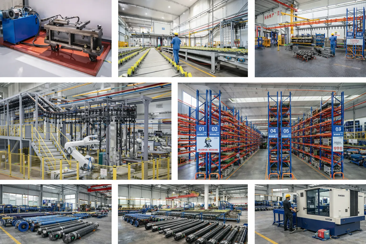
A 5,500 mm stroke cylinder requires a barrel length of approximately 6,000–6,500 mm (stroke plus piston length plus end cap depth). Machining a bore this long demands deep-hole boring equipment with exceptional straightness control — the bore centreline must not deviate more than 0.5 mm over the full length, or the piston will bind at full extension.
Korea Ever-Power's deep-hole boring capability extends to 6,000 mm depth — covering the full lateral shift cylinder range. After boring, the barrel is honed to Ra 0.2–0.4 µm over the entire stroke length. The rod is ground and chrome plated to matching straightness and finish standards. Because the rod must resist sag at full extension, Korea Ever-Power selects rod stock with verified straightness (bow ≤ 0.5 mm/metre) before chrome plating and grinding.
Every lateral shift cylinder is hydrostatic tested at 1.5× working pressure AND functionally tested for full-stroke extension at the specified traverse speed — verifying smooth, continuous motion without stick-slip or speed variation across the 5,500 mm travel.
OEM & ODM
FAQ
Related Categories
Další informace
| Editor |
|---|
Související produkty
-
Injection Molding Machine Reciprocating Cylinder (Mold Shifting Cylinder)
-
Cement Equipment Vertical Mill Cylinder
-
Filter Press Hydraulic Cylinder
-
Injection Molding Machine Shooting Cylinder
-
Hydraulic Press Master Cylinder
-
Hydraulic Press Tilt Cylinder
-
Hydraulic Press Side Cylinder
-
Hydraulic Press Return Cylinder


