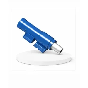
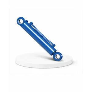
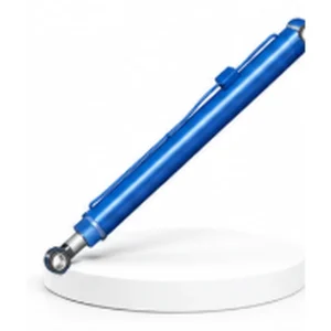
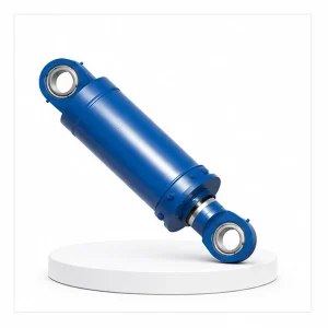
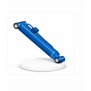
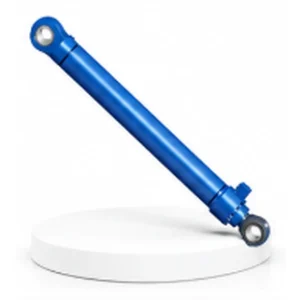
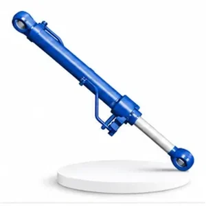
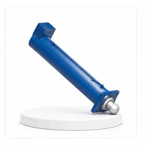
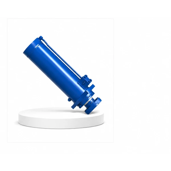
Mobile Crane Counterweight Cylinder

Why the Crane Needs 200 Tonnes Behind It Before Lifting 1 Tonne in Front
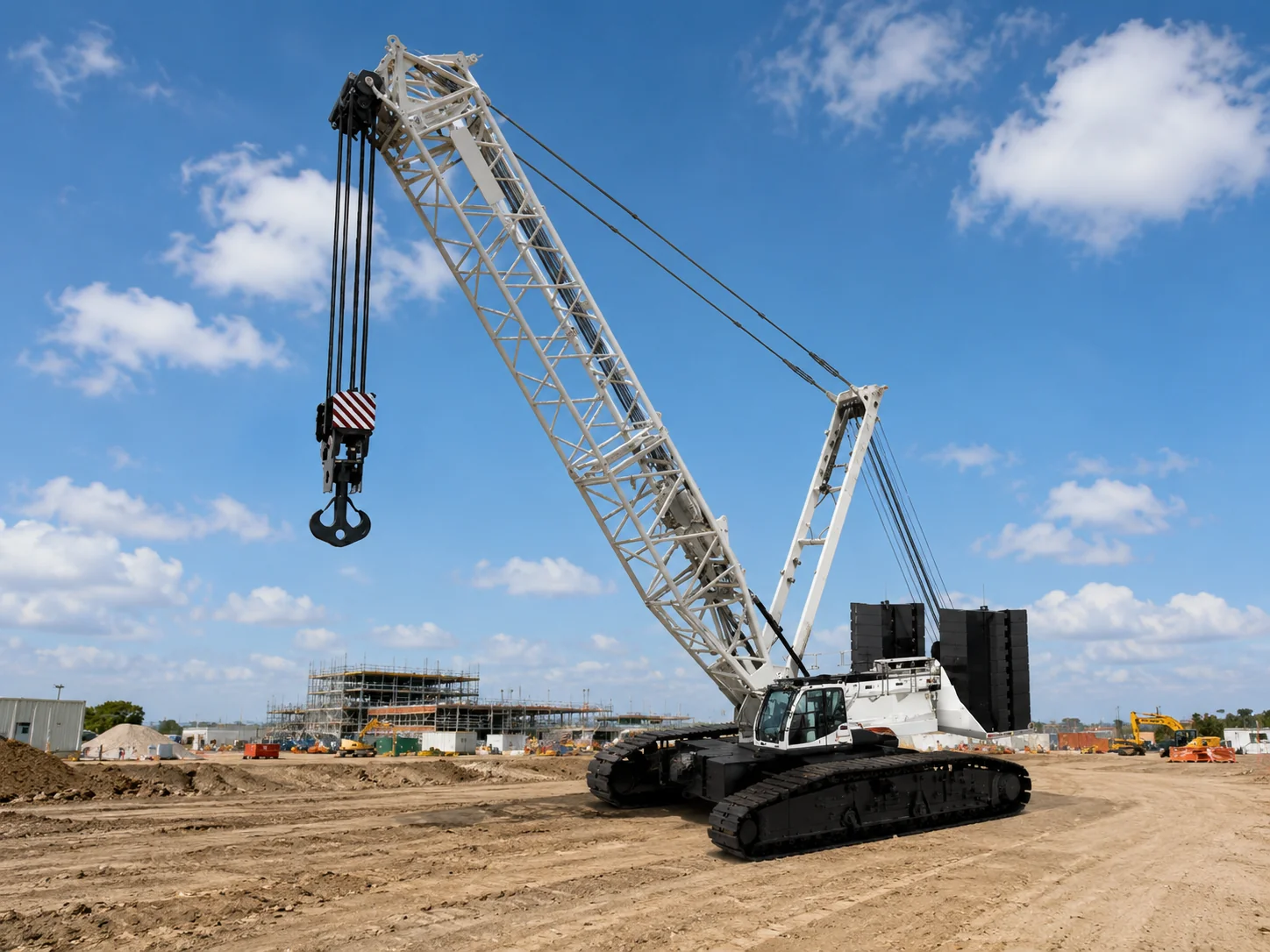
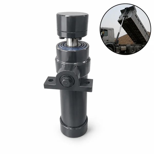
When a crane lifts a load at the boom tip, the load creates an overturning moment that tries to tip the crane forward. The counterweight — stacked on the rear of the superstructure, behind the slewing centre — creates an opposing moment that keeps the crane stable. On large cranes, the counterweight package outweighs the maximum load by 3–5× because the counterweight is closer to the crane's centre than the load is at the boom tip.
The counterweight slabs are too heavy for manual handling and too precisely positioned for ordinary crane lifting. Each slab must align with dowel pins on the crane's counterweight tray — a clearance of 5–10 mm between the slab's pin holes and the tray's pins. The counterweight cylinder provides the controlled, low-speed motion needed to guide each slab onto these pins without damage.
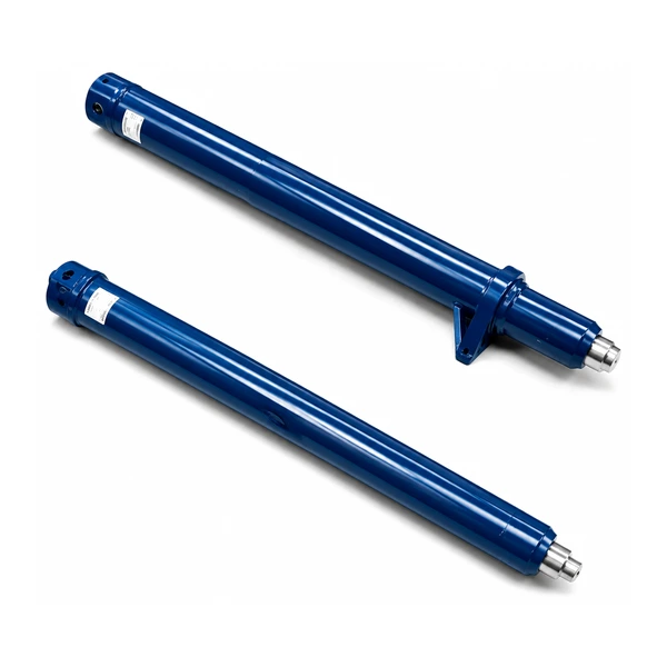
Korea Ever-Power manufactures counterweight cylinders for crane OEMs as part of the mobile machinery hydraulic cylinder range — from 25-tonne truck cranes (single counterweight slab) to 1,200-tonne crawler cranes (10+ stacked slabs).
Technical Specifications
| Parameter | Specification |
|---|---|
| Product | Mobile Crane Counterweight Cylinder |
| Function | Lift, position, and stack counterweight slabs |
| Bore Diameter | 85 mm – 320 mm |
| Rod Diameter | 55 mm – 180 mm |
| Stroke | ≤ 1,500 mm |
| Working Pressure | Maximum 35 MPa |
| Application | Mobile Crane (counterweight self-assembly system) |
| Certification | ISO 9001 · 100% hydrostatic tested · load-holding verified |
Self-Assembly — The Crane Builds Itself
Large mobile cranes cannot travel on public roads with their full counterweight installed — the combined weight would exceed bridge load limits and axle load regulations. The counterweight slabs travel separately on flatbed trailers and are assembled onto the crane at the job site. The counterweight cylinder enables "self-rigging" — the crane installs its own counterweight without needing a second crane to lift the slabs:
The counterweight slabs arrive on a low-bed trailer, positioned within reach of the crane's counterweight rigging system.
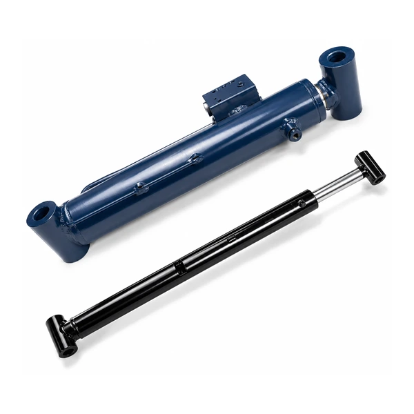
The counterweight mechanism — powered by this cylinder — hooks under the slab, lifts it from the trailer, and swings it toward the crane's rear tray. The lifting motion must be slow and controlled — a 20-tonne slab swinging uncontrolled would destabilise the crane before its counterweight is even installed.
The cylinder retracts slowly, lowering the slab until the pin holes align with the dowels on the counterweight tray. The operator guides the alignment visually or with camera assistance. Millimetre-level control at the end of stroke is essential — dropping a 20-tonne slab the last 10 mm off-centre can shear a dowel pin or crack the cast-iron tray.
Large cranes stack 5–12 slabs in sequence — each slab adds stability that allows the next (heavier) slab to be lifted. The first slab is the most critical: the crane has no counterweight yet, so the self-rigging load must be within the unballasted crane's stability limit. Contact the Korea Ever-Power engineering team for counterweight cylinder specifications.
Lowest Cycle Count, Highest Precision — A Cylinder That Works 20 Minutes per Job
The suspension cylinder (#20) cycles millions of times per year. The luffing cylinder (#17) cycles thousands of times per day. The counterweight cylinder cycles 5–12 times per job setup — once per slab, plus the same number to remove the slabs at teardown. On a crane that moves to a new site weekly, that is 10–24 cycles per week — fewer than 1,500 cycles per year.
Despite this low cycle count, each cycle demands exceptional precision. The slab must align with dowel pins to within ±5 mm. The lowering speed during the final 50 mm of placement must be controllable to less than 5 mm/second. Any sudden movement — from seal stiction, valve response lag, or hydraulic resonance — risks misalignment or impact damage. The counterweight cylinder uses the same proportional-valve-compatible port sizing and low-friction seals as the high-cycle crane cylinders — not because it needs cycle-life endurance, but because it needs smooth, precise motion control at very low speed.
The other demand is reliability during long idle periods. Between counterweight operations, this cylinder sits unused for hours, days, or weeks — exposed to weather, temperature cycles, and vibration from the crane's travel. Seals must not stick after extended static periods; the rod must not corrode during storage; and the load-holding valve must maintain the slab position during the entire crane operation without drift.
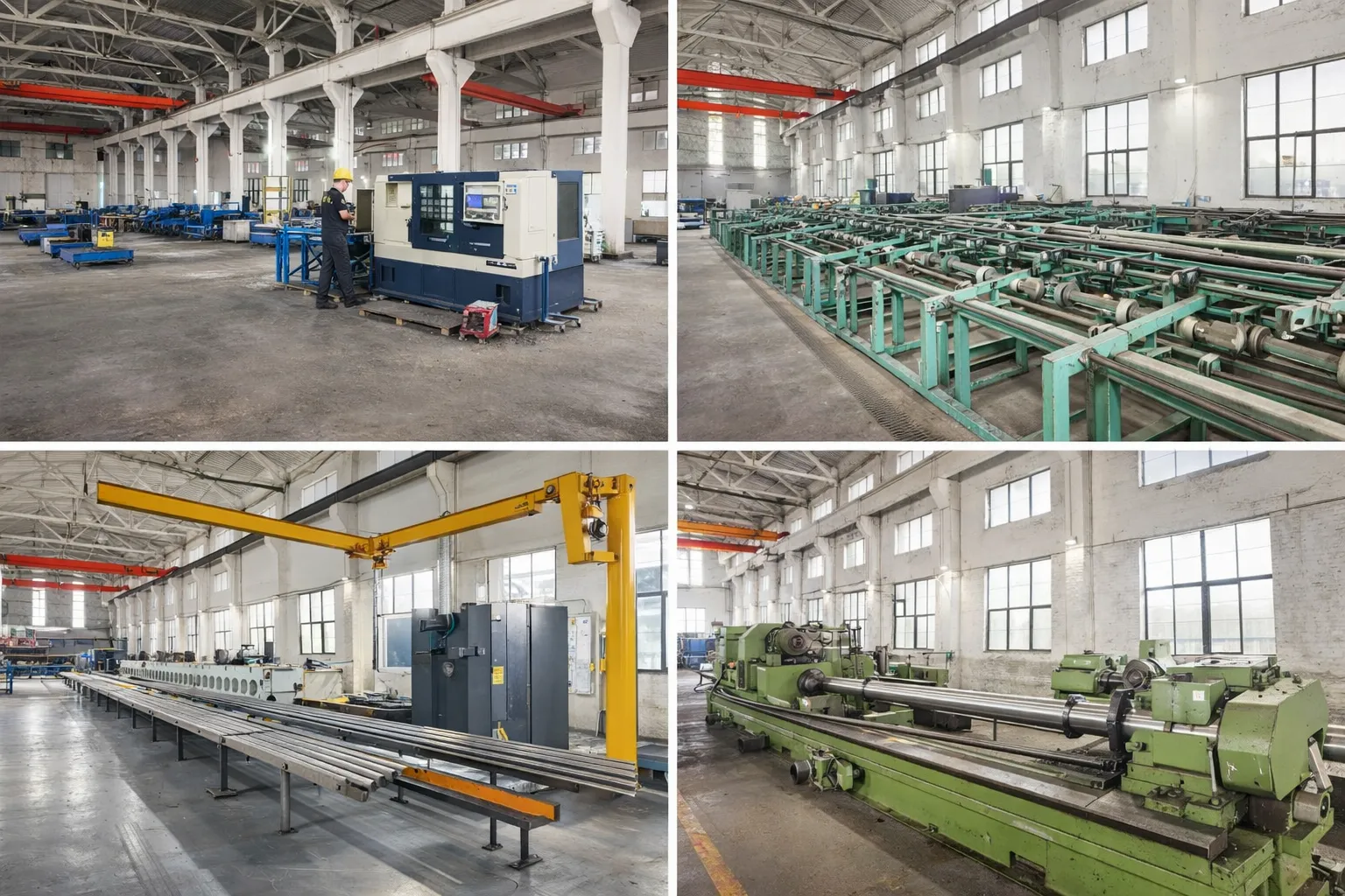
Manufacturing Process
The counterweight cylinder's bore (85–320 mm) is honed to Ra 0.2–0.4 µm. Chrome plating is 50–80 µm with a corrosion-resistant base layer — extended idle periods with partial rod exposure demand better storage protection than a continuously cycling cylinder. Rod eye forging and pin bore machining are held to H7/g6 fit tolerances for the counterweight mechanism's pivot connections. Seals are polyurethane with NBR wipers rated for -30 °C to +80 °C outdoor service.
Every counterweight cylinder is hydrostatic tested at 1.5× rated pressure (52.5 MPa), load-holding tested (verifying zero drift under rated slab weight for a defined hold period), and low-speed motion tested — verifying smooth, proportional extension and retraction at speeds below 5 mm/second without stick-slip. This low-speed test is unique to the counterweight cylinder and is not performed on the other crane cylinders whose minimum operating speed is much higher.
OEM & ODM
FAQ
Related Categories
Additional information
| Editor |
|---|