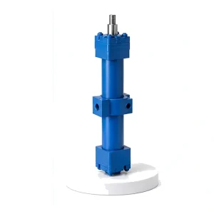
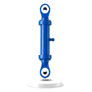
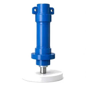
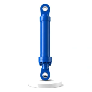
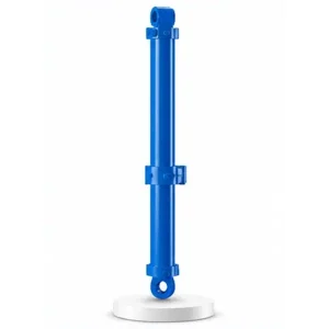
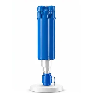
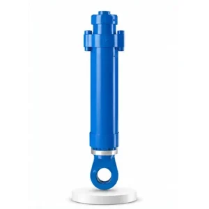
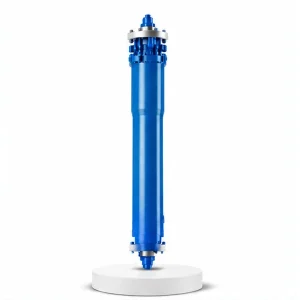
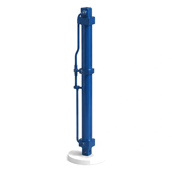
Mold Opening and Closing Hydraulic Cylinder for Vulcanizing Machine

Mold Opening & Closing Cylinder
4 Metres Up.
One Tire Out.
4 Metres Down.
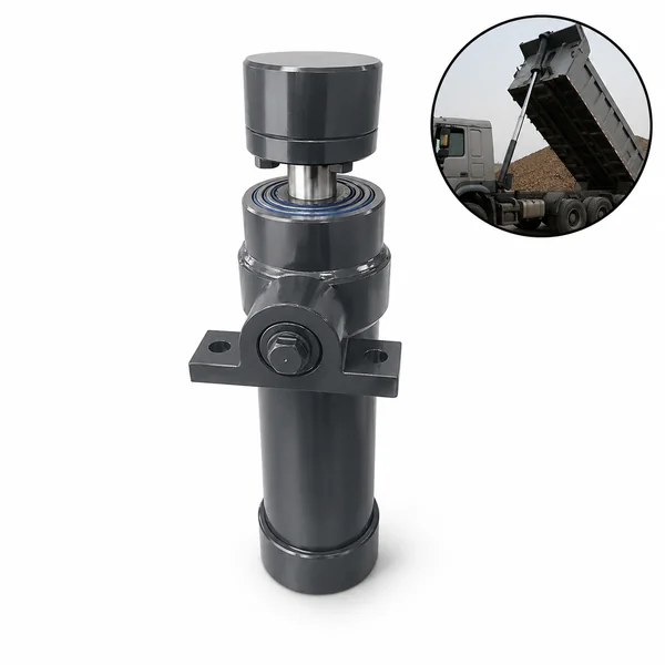
The injection moulding mold opening cylinder (#26) needs 700 mm of stroke — enough to separate two flat platens for a thin plastic part. The vulcanizing mold opening cylinder needs 4,000 mm — because a tire is not a flat part. The upper mold dome must lift high enough to clear the cured tire, the centre mechanism, and the loading arm that swings in to grab the tire. Same name, same function, 6× the stroke — because the product geometry demands it.
Why the Vulcanizing Mold Needs 4,000 mm of Opening — Not 700 mm
An injection mould opens just enough to separate two flat halves and drop out a thin plastic part — 300–700 mm is sufficient. A vulcanizing mold is different: the lower half is a deep container holding the bottom sidewall and most of the tread shape; the upper half is a dome that forms the top sidewall and the upper tread. The cured tire sits inside this container, partially enclosed by the centre mechanism (the bladder mandrel that shapes the tire's inner surface).
To remove the tire, the upper dome must rise far enough for the loading arm to swing horizontally between the dome and the tire — gripping the tire from above and lifting it out of the container. The clearance must accommodate the dome height (300–600 mm), the tire section height (150–400 mm), the loading arm mechanism (400–800 mm), and a safety margin for the operator's sight line. These clearances sum to 2,000–4,000 mm depending on the tire size and press layout. Korea Ever-Power manufactures the mold opening/closing cylinder as the motion actuator of the vulcanizing machine cylinder family.
Technical Specifications
| Parameter | Value |
|---|---|
| Product | Mold Opening and Closing Hydraulic Cylinder for Vulcanizing Machine |
| Function | Raise upper mold dome / lower it for closure |
| Bore Diameter | 50 mm – 140 mm |
| Rod Diameter | 28 mm – 100 mm |
| Stroke | ≤ 4,000 mm |
| Maximum Thrust | 384 KN (bore 140 mm / pressure 25 MPa) |
| Working Pressure | Up to 25 MPa |
| Certification | ISO 9001 · 100% hydrostatic tested |
Dome and Container — Why a Tire Mold Is Not Two Flat Halves
An injection mold has two flat-backed halves that bolt to flat platens. A vulcanizing mold has a fundamentally different geometry because a tire is a toroidal (doughnut-shaped) object that wraps around a centre mechanism.
Upper dome (top mold half): A curved dome shape that forms the top sidewall of the tire — including the sidewall lettering, DOT markings, and the upper bead seat. The dome is heated by steam channels and lifts vertically when the mold opening cylinder retracts.
Lower container (bottom mold half): A deep container that holds the tread segments (on segmented molds) and forms the bottom sidewall. The container stays on the press bed — it does not move. The cured tire sits in this container after the dome lifts.
Centre mechanism (bladder assembly): A vertical post in the centre of the mold that carries the rubber bladder. The bladder inflates inside the green tire during cure, pressing the rubber outward into the mold cavity. After cure, the bladder deflates and retracts. The centre mechanism protrudes upward from the container — the dome must lift high enough to clear this protrusion before the loading arm can access the tire.
The Opening Sequence — Five Steps, Three Cylinders
The mold opening is not a single motion — it is a coordinated sequence involving three different vulcanizing machine cylinders:
Clamping force released in 1–3 seconds. The bladder deflates simultaneously. The mold halves are now unloaded but still touching.
The initial pull separates the dome from the tire's upper sidewall — breaking the adhesion between the cured rubber and the hot mold surface. This break-free force is the highest load the opening cylinder sees.
Fast upward traverse — the dome clears the centre mechanism, rises above the tire, and stops at the maximum opening height. Speed matters: every second of mold-open time is a second the mold cools, wasting energy on reheat.
The loading arm swings in horizontally, grips the tire, lifts it out of the container, and transfers it to the tipping mechanism (#28).
The loading arm places a new green tire in the container. The mold opening/closing cylinder lowers the dome. The pressurized cylinder engages clamping force. The next cure cycle begins. Contact the hydraulic cylinder engineering team for complete vulcanizing press cycle specifications.
Hot Mold, Long Stroke — Three Engineering Challenges the Injection Cylinder Never Faces
At 180 °C, the steel mold and press frame expand by 1–3 mm compared to room temperature. The cylinder's "fully closed" position at operating temperature is not the same as at cold start-up. The control system must compensate — using the pressurized cylinder's force (not the opening cylinder's position) to confirm full mold closure. The opening cylinder must accommodate this thermal growth within its stroke range.
The force needed to break the dome free from the cured tire's sidewall depends on the rubber compound, the mold release agent application, and the cure temperature. Some high-performance rubber compounds adhere more aggressively to the mold surface — requiring the opening cylinder to deliver a higher break-free force than standard passenger car tire formulations. Korea Ever-Power sizes the bore to handle the worst-case adhesion force in the customer's product range.
When the mold is closed, the cylinder rod is retracted inside the barrel — protected. When the mold opens fully, 4 metres of chrome rod is exposed to the hot air rising from the open mold (60–120 °C). FKM seals and heavy chrome plating (50–80 µm) protect against the thermal environment, and the same long-stroke buckling and rod-droop considerations from the cement roll over cylinder (#22) apply here.
Manufacturing — Long Stroke, Hot Environment, Vertical Duty
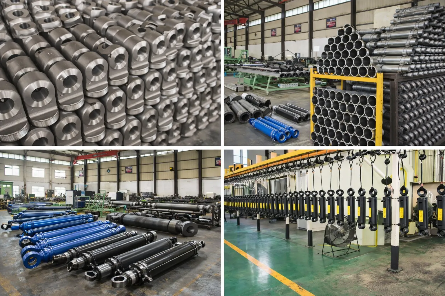
The mold opening/closing cylinder combines two engineering challenges that appear separately in other products: the long stroke of the cement roll over cylinder (#22) and the hot environment of the pressurized vulcanizing cylinder (#29). Korea Ever-Power applies both skill sets to this cylinder.
The rod is buckling-verified for the specific press frame geometry (typically vertical mounting — the rod hangs downward from the press crown, supporting the dome weight). The rod chrome plating is 50–80 µm for thermal and corrosion resistance. FKM seals accommodate the 60–120 °C ambient temperature at the cylinder's mounting position. The bore is honed to Ra 0.2–0.4 µm over the full 4-metre stroke length — requiring a long-stroke honing pass that maintains uniform surface finish from end to end.
Every mold opening/closing cylinder is hydrostatic tested at 1.5× working pressure (37.5 MPa) and functionally tested for full 4-metre extend and retract with cushion verification at both the open and closed positions.
OEM & ODM
FAQ
Related Categories
Additional information
| Editor |
|---|