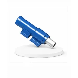
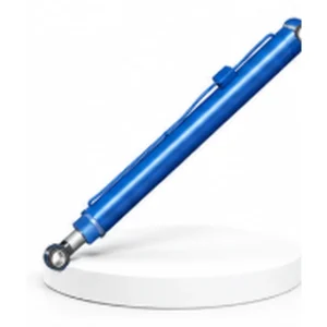
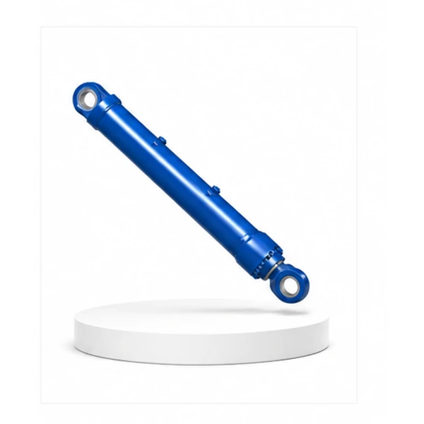
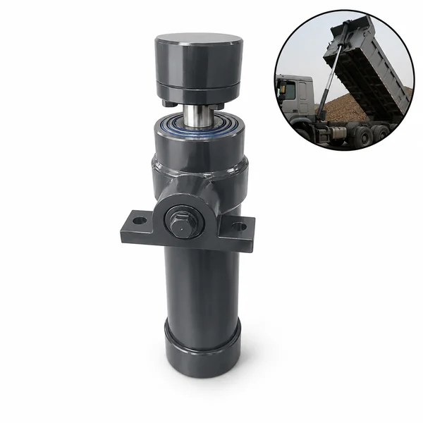
Rotary Drilling Luffing Cylinder


From Cranes to Drilling Rigs — A Different Kind of Luffing
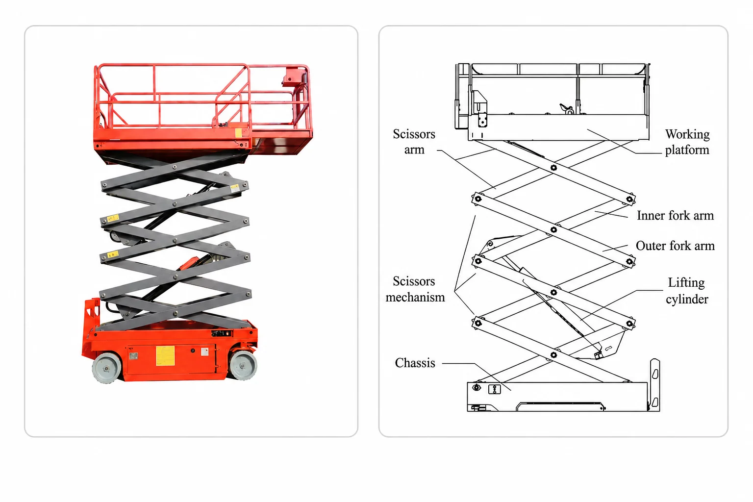
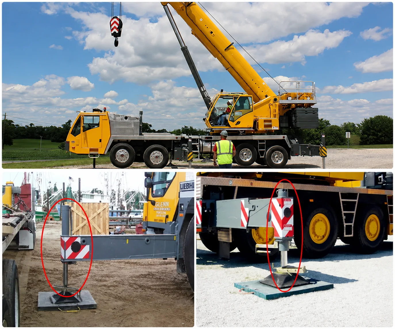
The mobile crane luffing cylinder (#17) changes the boom angle during every lift — continuously adjusting between 20° and 85° throughout the working day. The rotary drilling luffing cylinder does something fundamentally different: it sets the mast to vertical once at the start of the job, holds it there for hours or days of continuous drilling, then folds it flat for transport. The crane luffing cylinder is a dynamic actuator; the drilling luffing cylinder is a precision positioner.
The key engineering difference is the verticality requirement. A crane boom at 45.5° instead of 45.0° changes the working radius by a few centimetres — acceptable for most lifts. A drilling mast at 89.7° instead of 90.0° puts the borehole 260 mm off-target at 50 metres depth — unacceptable for a foundation pile that must land within 75 mm of the design position.
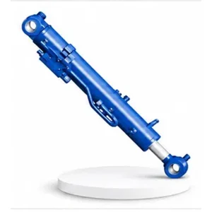
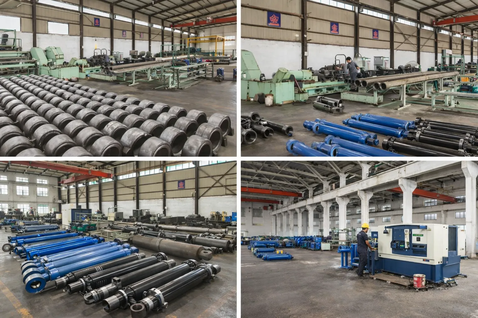
Korea Ever-Power manufactures the rotary drilling luffing cylinder as the first of three rotary drilling rig cylinders in the mobile machinery hydraulic cylinder range — alongside the mast cylinder (#25) and the pressurized cylinder (#26).
Technical Specifications
| Parameter | Specification |
|---|---|
| Product | Rotary Drilling Luffing Cylinder |
| Function | Control the mast luffing angle — adjust distance between mast and chassis |
| Bore Diameter | 125 mm – 250 mm |
| Rod Diameter | 90 mm – 160 mm |
| Stroke | ≤ 1,640 mm |
| Working Pressure | Up to 32 MPa |
| Application | Rotary Drilling Rig (foundation piling) |
| Certification | ISO 9001 · 100% hydrostatic tested · verticality-hold verified |
±0.3° — The Verticality Tolerance That Every Foundation Depends On
A bored pile is drilled vertically into the earth to carry the weight of a building column, bridge pier, or retaining wall. The pile's design position is specified to within 75 mm of the column centreline. At 30 metres drilling depth, a verticality error of just 0.15° displaces the pile toe by 75 mm — the entire tolerance budget. The luffing cylinder must hold the mast to within ±0.3° of true vertical during the entire drilling operation.
The rotary table at the top of the mast applies 200–500 KNm of torque to the drilling tool. The reaction to this torque tries to twist the mast sideways — the luffing cylinder resists this twisting force, holding the mast vertical against the drilling torque. Larger-diameter piles (1.5–3.0 m) require more torque, which increases the side-loading on the luffing cylinder.
When the drill tool is pulled out of the borehole (to empty the soil from the bucket), the mast carries the full weight of the kelly bar and the soil-laden drilling bucket — potentially 10–30 tonnes at the top of a 25-metre mast. The luffing cylinder must hold the mast angle against this vertical load without deflection. Contact the Korea Ever-Power engineering team for rotary drilling cylinder specifications.
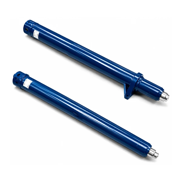
Two Extremes — Vertical for Drilling, Flat for Transport
The drilling mast stands 20–30 metres tall when vertical — far too high for road transport (legal height limit is 4.0–4.5 metres). The luffing cylinder must fold the mast from vertical (90°) to near-horizontal (5–10°) for transport, then erect it to vertical at the next job site. The 1,640 mm stroke converts to approximately 80° of mast rotation through the mast's pivot linkage.
Erecting the mast is the highest-force operation for the luffing cylinder — the mast's centre of gravity is furthest from the pivot when the mast is horizontal, producing maximum gravitational torque. As the mast approaches vertical, the torque decreases rapidly. The cylinder must deliver maximum force at the start of the erection stroke and controlled precision at the end — transitioning from a power actuator to a precision positioner within the same stroke.
Manufacturing Process
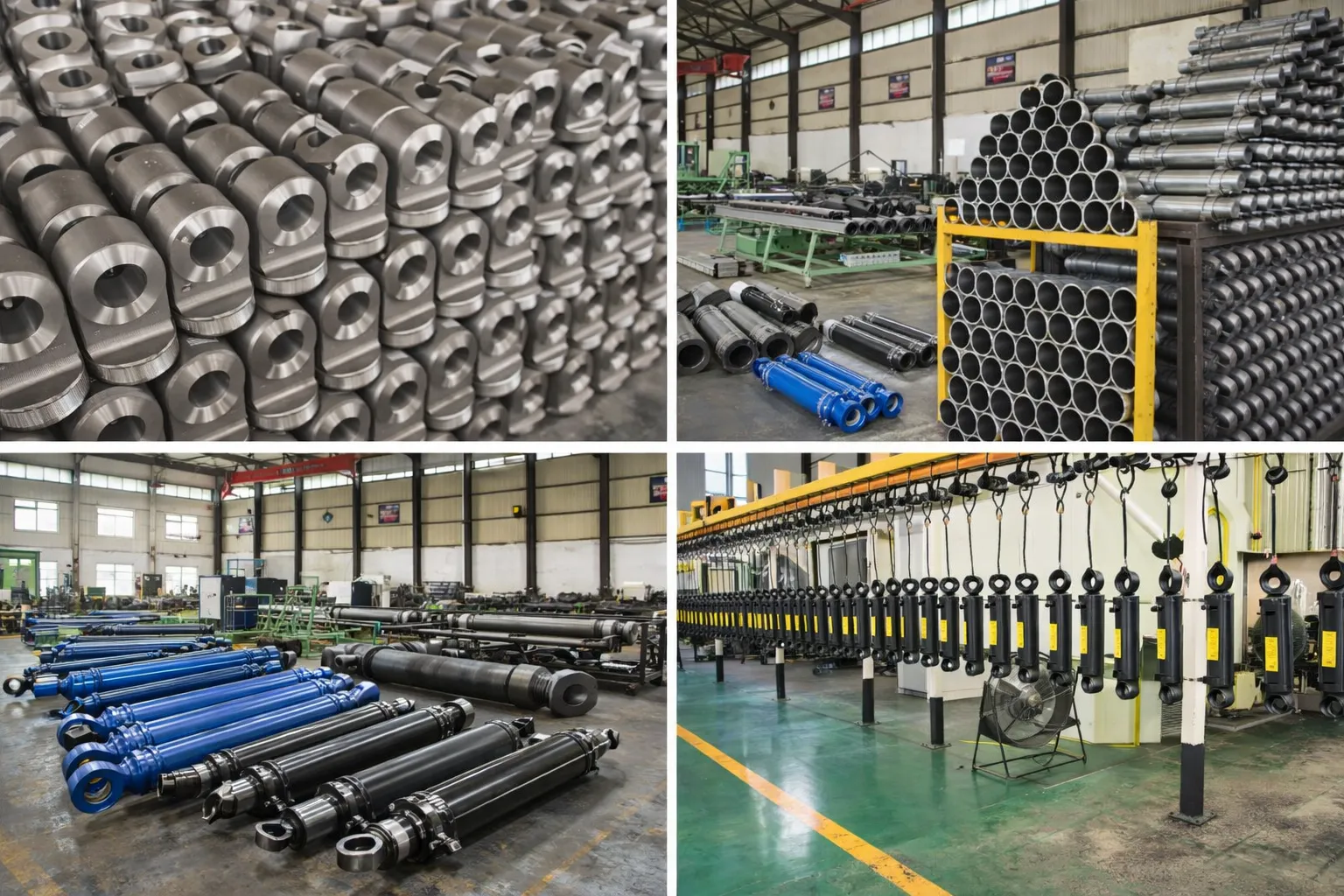
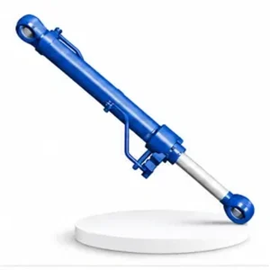
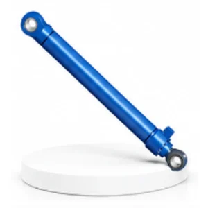
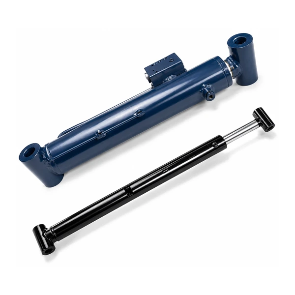
The bore (125–250 mm) is honed to Ra 0.2–0.4 µm. Chrome plating is 50–80 µm (outdoor construction site service). The rod eye bearing is a heavy-duty spherical joint — accommodating the angular misalignment between the cylinder and the mast pivot as the mast rotates through 80° of travel. A standard clevis pin would bind at extreme angles; the spherical joint maintains free rotation throughout the full mast erection arc.
Load-holding is provided by a counterbalance valve on the rod port — preventing the mast from collapsing if a supply hose fails. The counterbalance valve's crack pressure is set to hold the mast at any angle between 10° and 90° with a safety factor of ≥1.5. Every rotary drilling luffing cylinder is hydrostatic tested at 1.5× working pressure (48 MPa) and verticality-hold tested — the cylinder is loaded to simulate the mast weight at vertical position, the pump disconnected, and the position monitored for zero drift over a defined period.
OEM & ODM
FAQ
Related Categories
Informations complémentaires
| Editor |
|---|