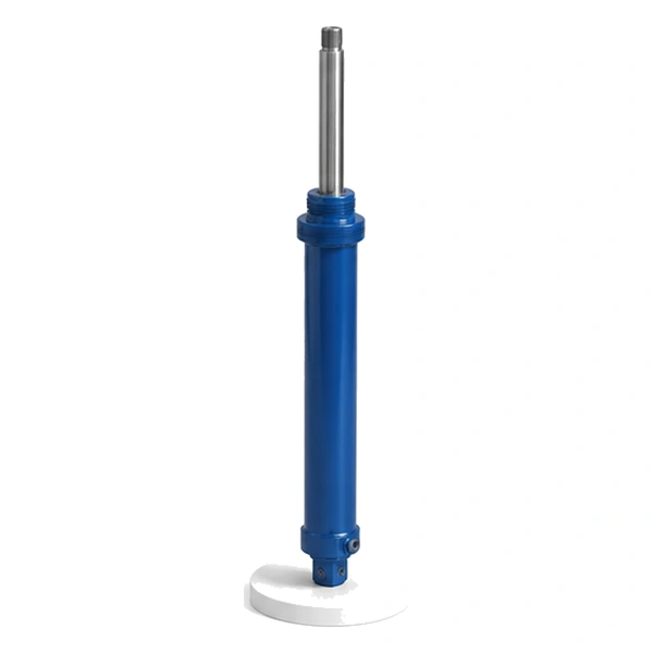
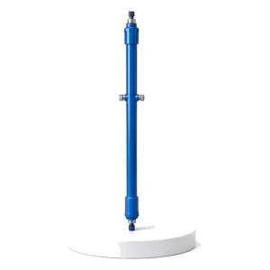
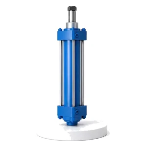
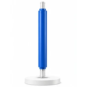
Upper Ring Hydraulic Cylinder for Vulcanizing Machine

Upper Ring Cylinder · Centre Mechanism
0.5 mm Off-Centre
at the Bead =
Vibration at 120 km/h
Deep inside the vulcanizing press — at the very centre of the mold — the centre mechanism grips the tire by its two bead wires and shapes it against the bladder before the mold closes. The upper ring cylinder drives the upper chuck of this mechanism: lowering it to grip the upper bead, holding it concentric during shaping and cure, then raising it to release the cured tire. If the upper bead is 0.5 mm off-centre, the tire has radial force variation — the steering wheel shimmy that sends a tire back for warranty.
The Centre Mechanism — The Mechanical Heart of the Tire Press
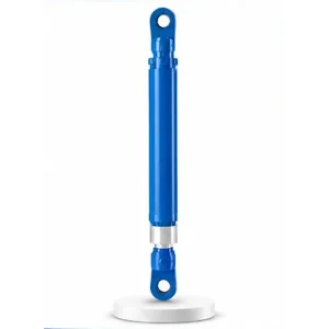
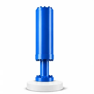
The previous vulcanizing cylinders (#28–#30) handle the mold — clamping it, opening it, flipping the finished tire. The upper ring cylinder is the first of two cylinders (#31, #32) that handle the tire itself — specifically, its bead wires. These cylinders are part of the centre mechanism, a vertical assembly mounted at the centre of the lower mold container.
The centre mechanism consists of a central post, the rubber bladder (which inflates inside the tire during cure), the upper bead chuck (driven by this cylinder), the lower bead chuck (driven by the lower ring cylinder #32), and the shaping air/steam supply lines. Together, these components grip the green tire by both beads, inflate the bladder to shape the tire against the mold cavity, and hold everything concentric during the 10–30 minute cure cycle. Korea Ever-Power manufactures the upper ring cylinder as part of the vulcanizing machine cylinder family.
Technical Specifications
| Parameter | Value |
|---|---|
| Product | Upper Ring Hydraulic Cylinder for Vulcanizing Machine |
| Function | Drive the upper bead chuck for tire loading and shaping |
| Bore Diameter | 50 mm – 140 mm |
| Rod Diameter | 28 mm – 100 mm |
| Stroke | ≤ 1,000 mm |
| Maximum Thrust | 384 KN (bore 140 mm / pressure 25 MPa) |
| Working Pressure | Up to 25 MPa |
| Certification | ISO 9001 · 100% hydrostatic tested |
Why Bead Concentricity Determines Tire Uniformity
A tire's "uniformity" is how evenly it rolls — how consistent the force is at every point of the rotation. Perfect uniformity means the tire pushes the road with exactly the same force at every degree of rotation. Any variation is called "radial force variation" (RFV) — the primary cause of steering wheel vibration at highway speed.
RFV is largely determined during vulcanization — specifically by how concentrically the two bead wires are positioned in the mold. The beads are the structural anchors of the tire: the entire carcass (the internal structure of plies and belts) is stretched between the upper and lower beads. If one bead is off-centre by even 0.5 mm, the carcass tension is uneven — creating a thicker, stiffer zone on one side and a thinner, more flexible zone on the opposite side. This asymmetry produces RFV that cannot be corrected after curing.
The upper ring cylinder positions the upper bead chuck — and the concentricity of the upper bead is a direct function of the cylinder's rod alignment, the chuck's concentricity on the centre post, and the cylinder's ability to hold the chuck at the exact axial position during bladder inflation (which applies lateral forces on the chuck that try to shift it).
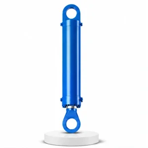
Upper Ring + Lower Ring — A Pair That Grips Both Beads
The tire has two bead wires — upper and lower. The centre mechanism uses two ring cylinders to grip both:
The distance between the upper and lower chuck positions during cure sets the tire's section height — the vertical dimension of the tire. If the upper ring cylinder does not hold its position to the specified tolerance, every tire produced in that press has a different section height — failing the dimensional specification. Contact the hydraulic cylinder engineering team for centre mechanism cylinder specifications.
The Shaping Sequence — How the Upper Ring Cylinder Transforms a Flat Tube into a Tire Shape
The green tire arrives at the press as a roughly cylindrical shape — the beads are close together and the sidewalls are nearly vertical. During "shaping," the centre mechanism transforms this cylinder into the toroidal (doughnut) shape of a finished tire:
The upper ring cylinder lowers the upper chuck onto the upper bead. The lower chuck rises to grip the lower bead. Both beads are now clamped. The green tire hangs between the chucks like a drum.
The upper ring cylinder retracts partially — bringing the upper bead downward, closer to the lower bead. This reduces the bead-to-bead distance, which forces the sidewalls to bulge outward — starting the transformation from cylinder to torus.
Low-pressure shaping air (1–3 bar) inflates the bladder inside the tire. The bladder pushes the sidewalls outward into the toroidal shape. The upper ring cylinder holds the upper chuck at the exact bead-to-bead distance — resisting the bladder's upward push on the upper bead.
The mold opening cylinder (#30) lowers the dome onto the shaped tire. The pressurized cylinder (#29) applies clamping force. The bladder pressure increases to 15–25 bar with steam/hot water. The upper ring cylinder holds position throughout the 10–30 minute cure — maintaining bead concentricity against the full bladder pressure.
Manufacturing — Precision for Concentricity
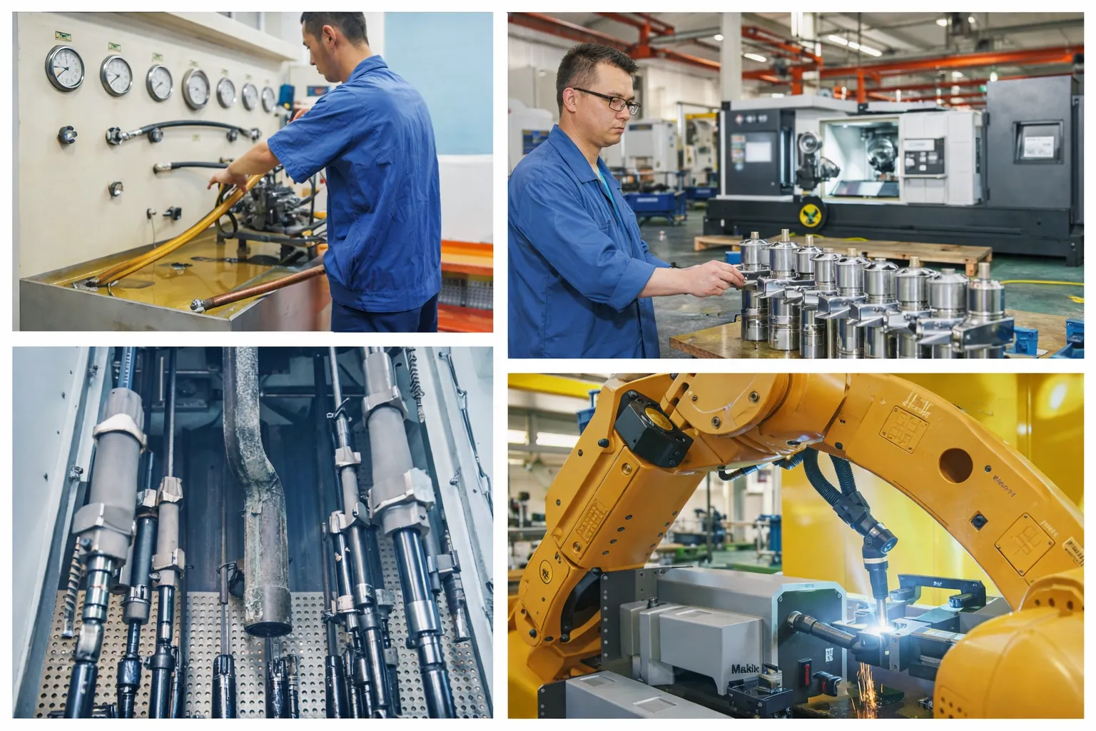
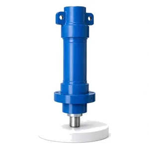
The upper ring cylinder operates inside the centre mechanism — a thermally stressed, mechanically constrained space at the very centre of the mold. The rod must run concentric with the centre post to within tight tolerances — any rod misalignment translates directly into upper bead misalignment, which becomes tire RFV.
The bore is honed to Ra 0.2–0.4 µm. The rod concentricity to the bore axis is verified to ≤0.1 mm TIR (total indicated runout) — tighter than the standard for non-precision cylinders. FKM seals are standard (the centre mechanism is heated to 150–180 °C by the bladder steam). Chrome plating is 50–80 µm for thermal resistance and the inevitable contact with rubber fumes and cure by-products.
Every upper ring cylinder is hydrostatic tested at 1.5× working pressure and position-hold tested — verifying that the cylinder holds its set position (simulating the bead-to-bead distance hold) against a simulated bladder-pressure load without drift during a defined hold period.
OEM & ODM
FAQ
Related Categories
追加情報
| Editor |
|---|
関連商品
-
Tipping Cylinder for Vulcanizing Machine
-
Injection Molding Machine Reciprocating Cylinder (Mold Shifting Cylinder)
-
Injection Molding Machine Mold Opening and Closing Cylinder
-
Hydraulic Press Cushion Cylinder
-
Injection Molding Machine Ejection Cylinder
-
Hydraulic Press Front Side Shift Cylinder
-
Hydraulic Press Side Cylinder
-
Hydraulic Press Leveling Cylinder


