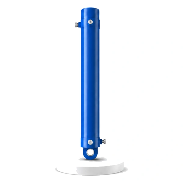
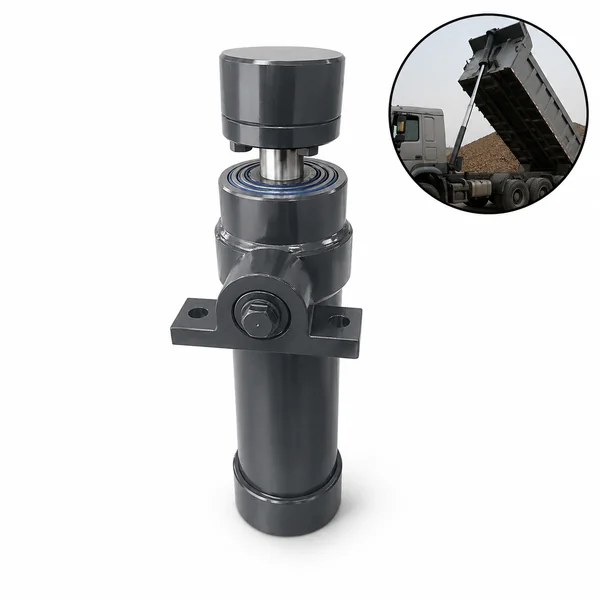
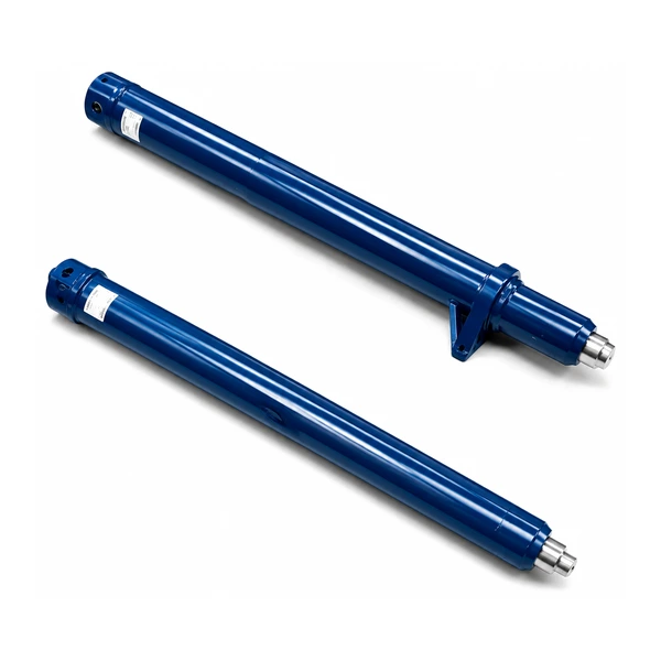
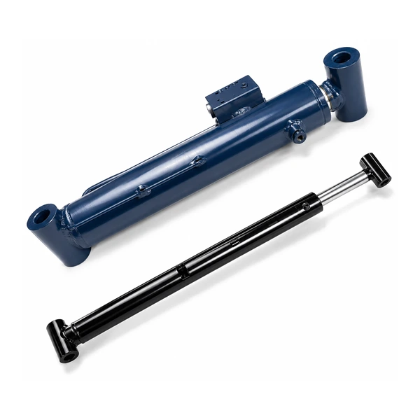
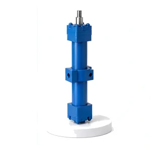
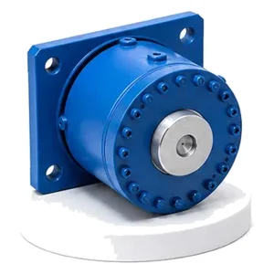
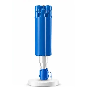
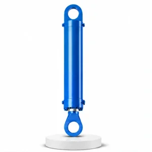
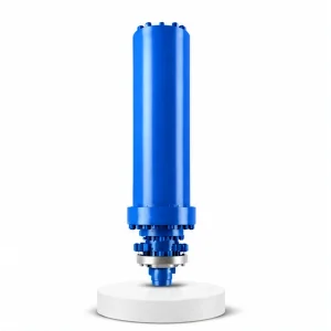
Cement Equipment Roll over Cylinder

Roll Over Cylinder
6 Metres of Stroke.
A Few Times per Year.
Zero Tolerance for Failure.
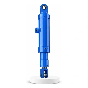
The grinding cylinders (#20, #21) run 24/7 with a 500 mm stroke. The roll over cylinder operates a few times a year — but with a 6,000 mm stroke. It swings the entire grinding roller assembly outward from the mill body for maintenance: roller surface inspection, table liner replacement, and rocker arm bearing service. If this cylinder fails mid-swing, the roller assembly hangs unsupported — a multi-tonne load suspended at an awkward angle with no easy recovery.
What "Roll Over" Means — Swinging 30 Tonnes of Roller Assembly Out of the Mill
Inside a vertical roller mill, the grinding rollers are enclosed within the mill housing — accessible only through inspection doors too small for major maintenance. When the roller surface needs resurfacing (worn rollers are re-welded on site), the table liners need replacing, or the rocker arm bearings need service, the entire roller assembly must be swung outward from the mill body. This operation is called "roll over."
The roll over cylinder lifts and swings the grinding roller, its rocker arm, and the roller shaft assembly — typically 20–50 tonnes — through a large arc on a hinge mechanism mounted on the mill housing. The assembly rotates outward until the roller is fully clear of the mill, accessible at ground level for crane access, welding, and inspection. The 6,000 mm stroke provides the travel needed to swing through this arc — from the operating position deep inside the mill to the fully-open maintenance position outside it. Korea Ever-Power manufactures roll over cylinders as part of the industrial engineering hydraulic cylinder programme for cement equipment.
Technical Specifications
| Parameter | Value |
|---|---|
| Product | Cement Equipment Roll Over Cylinder |
| Function | Swing the roller assembly outward for maintenance |
| Bore Diameter | 180 mm – 320 mm |
| Rod Diameter | 110 mm – 170 mm |
| Stroke | ≤ 6,000 mm (longest in cement range) |
| Maximum Thrust | 1,688 KN (bore 320 mm / pressure 21 MPa) |
| Working Pressure | Up to 21 MPa |
| Certification | ISO 9001 · 100% hydrostatic tested |
Why 6,000 mm — The Geometry of a Full Swing-Out
The grinding cylinders (#20, #21) need only 500 mm of stroke — enough to adjust the roller gap by a few centimetres. The roll over cylinder needs 12 times more because it swings the roller assembly through an arc of 60–90° on a hinge that is 3–5 metres from the cylinder attachment point.
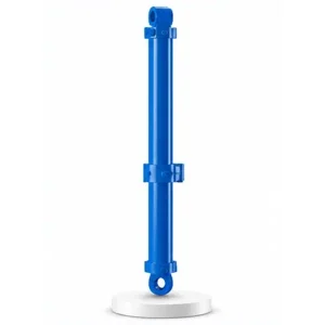
The geometry is a lever-and-pivot arrangement: the roll over hinge is on the mill housing side wall, the cylinder connects to the rocker arm frame at a distance from the hinge, and the roller is at the far end. As the cylinder extends, it pushes the frame outward, rotating the roller assembly around the hinge. The arc length at the cylinder attachment point — not the arc length at the roller — determines the cylinder stroke. For a hinge radius of 3 metres and a 90° swing, the arc length at the attachment point is approximately π × 3 / 2 ≈ 4.7 metres. The 6,000 mm maximum stroke provides margin for larger mill geometries and wider swing angles.
A 6,000 mm stroke on a 320 mm bore creates a very long, slender cylinder. Buckling resistance is a critical engineering consideration — the cylinder must be checked for Euler column buckling under the full 1,688 KN load at maximum extension. Korea Ever-Power verifies the buckling safety factor using the specific mounting geometry (pin-to-pin length, mounting angle) for each customer's mill installation.
Four Cement Cylinders — Each Serves a Different Phase
Korea Ever-Power manufactures four cylinder types for cement plant equipment. They look like a family, but each operates at a different speed, duty cycle, and purpose within the plant:
| # | Cylinder | Stroke | MPa | Purpose | Duty |
|---|---|---|---|---|---|
| 20 | Roller Press | ≤500 | 14 | Push rollers together | 24/7 continuous |
| 21 | Vertical Mill | ≤500 | 14 | Press roller onto table | 24/7 continuous |
| 22 | Roll Over | ≤6,000 | 21 | Swing roller out | Few times/year |
| 23 | Feeding | TBD | TBD | Drive grate cooler bed | Continuous reciprocating |
The roll over cylinder operates the least frequently but carries the highest per-operation risk — any failure during the swing leaves a multi-tonne assembly in a hazardous intermediate position.
Engineering Concern — What Happens if the Cylinder Fails Mid-Swing
The roll over cylinder is extended infrequently — but when it operates, the roller assembly is in transit between two stable positions (closed inside the mill, or fully open outside). At any intermediate position, the assembly's weight is partially supported by the cylinder and partially by the hinge. If the cylinder loses pressure mid-swing, the assembly's weight drives it to an uncontrolled position — either slamming back into the mill or swinging outward under gravity, depending on the hinge geometry.
A pilot-operated load-holding valve (counterbalance valve) on the cylinder prevents the roller assembly from moving if hydraulic pressure is lost. The valve locks the oil in the cylinder — holding the assembly at whatever position it occupied when the failure occurred. The maintenance crew can then bring a mobile hydraulic power unit to complete or reverse the swing safely.
Once the roller assembly reaches the fully-open position, a mechanical latch or prop secures it — transferring the load from the cylinder to the latch. The cylinder can then be depressurised safely. This ensures that maintenance crews working under the swing-out assembly are never relying on hydraulic pressure alone for safety.
The roll over operation is performed at low hydraulic flow — keeping the swing speed slow enough for the operator to stop the motion at any point. Typical swing time for the full 6-metre stroke is 5–15 minutes (not seconds). This slow speed ensures controllability and gives the operator time to react to any misalignment, interference, or unexpected load change during the swing.
Korea Ever-Power designs every roll over cylinder with load-holding valve provisions, mechanical latch interface details, and slow-speed circuit recommendations as standard deliverables. Contact the hydraulic cylinder engineering team for roll over cylinder specifications.
Long-Stroke Engineering — Buckling, Alignment, and Storage
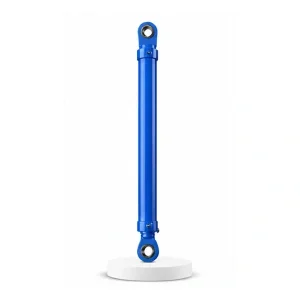
A 6-metre stroke on a 180–320 mm bore creates a cylinder that is extremely long relative to its diameter. This length ratio introduces engineering considerations that short-stroke grinding cylinders never face.
Euler buckling. At full extension under load, the rod acts as a long, slender column. The critical buckling load must exceed the working thrust by a safety factor of 3:1 or more. Korea Ever-Power selects the rod diameter not only for hydraulic force but for buckling resistance at the specific pin-to-pin distance and mounting angle of each installation — a rod that is hydraulically adequate may be structurally inadequate if the mounting geometry creates a long unsupported column.
Rod droop and guide bearing wear. A 6-metre rod extending horizontally from the barrel sags under its own weight. This sag loads the rod guide bearing unevenly — the bottom of the bearing carries more load than the top. Over time, this asymmetric loading wears the guide bearing into an oval, degrading the rod seal concentricity and eventually causing a leak. Korea Ever-Power specifies oversized guide bearings for long-stroke horizontal installations.
Long-term storage position. The roll over cylinder spends 99% of its life in the retracted position (roller assembly inside the mill). During this idle period, the retracted rod surface is protected inside the barrel — but the barrel end and port connections are exposed to cement dust for months. Korea Ever-Power specifies protective port caps and recommends a monthly partial-stroke exercise cycle to circulate oil through the seals and prevent static seal degradation.
OEM & ODM
FAQ
Related Categories
추가 정보
| Editor |
|---|
연관 상품
-
Tipping Cylinder for Vulcanizing Machine
-
Pressurized Hydraulic Cylinder for Vulcanizing Machine
-
Electric Furnace Lock Cylinder
-
Hydraulic Press Lateral Shift Anvil Cylinder
-
Electric Furnace Mast Cylinder
-
Hydraulic Press Clamping Cylinder
-
Hydraulic Press Leveling Cylinder
-
Hydraulic Press Master Cylinder


