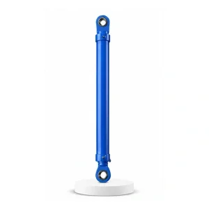
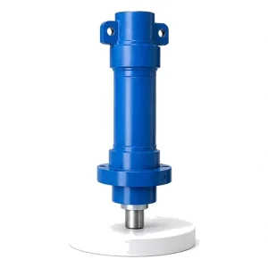
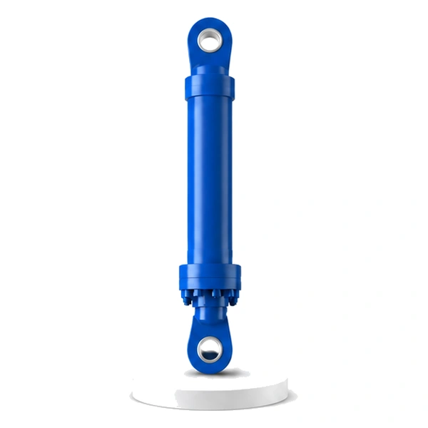
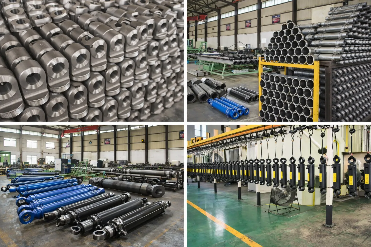
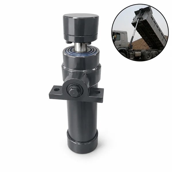
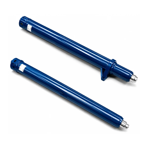
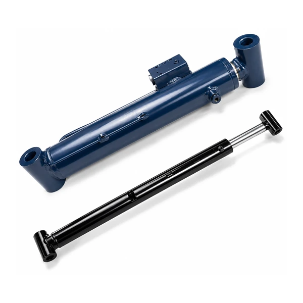
Cement Equipment Feeding Cylinder

Feeding Cylinder · Grate Cooler
Millions of Cycles per Year.
1,400 °C Clinker Overhead.
The grinding cylinders hold a constant force. The roll over cylinder swings once and waits. The feeding cylinder reciprocates — push forward, pull back, push forward, pull back — 5 to 20 strokes per minute, every minute of every day, while white-hot clinker from the kiln tumbles across the grate plates directly above it. No other cylinder in the cement plant accumulates this many cycles in this much heat.
How a Grate Cooler Works — And Why It Needs Reciprocating Cylinders
Clinker — the hard, nodular intermediate product of cement — falls from the rotary kiln at 1,200–1,400 °C onto a grate cooler. The cooler is a long, flat bed of perforated steel grate plates. Cooling air is blown upward through the perforations, cooling the clinker from kiln temperature to approximately 100 °C by the time it reaches the discharge end. The hot air rising from the clinker bed is recovered and used as combustion air in the kiln — a critical energy recovery step that determines the plant's overall thermal efficiency.
The clinker does not move across the cooler by gravity alone — the grate bed is nearly horizontal. Instead, the grate plates are arranged in alternating rows: fixed rows and moving rows. The feeding cylinders push the moving rows forward (carrying the clinker with them), then retract them (the clinker stays behind because it rests on both moving and fixed plates). The next push advances the clinker another step. This "walking floor" principle transports the clinker steadily from the kiln end to the discharge end. Korea Ever-Power manufactures feeding cylinders as part of the industrial engineering hydraulic cylinder programme.
Technical Specifications
| Parameter | Value |
|---|---|
| Product | Cement Equipment Feeding Cylinder |
| Function | Drive the reciprocating grate plates of the clinker cooler |
| Bore Diameter | 80 mm – 140 mm |
| Rod Diameter | 45 mm – 80 mm |
| Stroke | ≤ 1,200 mm |
| Maximum Thrust | 385 KN (bore 140 mm / pressure 25 MPa) |
| Working Pressure | Up to 25 MPa (highest in cement range) |
| Certification | ISO 9001 · 100% hydrostatic tested |
The Numbers — Why Cycle Count Changes Everything
The feeding cylinder reciprocates at 5–20 strokes per minute. Each stroke is a full extend-retract cycle. The numbers accumulate fast:
Five million full-stroke cycles per year. Every cycle loads and unloads the piston seal, passes the rod through the wiper, reverses the oil flow, and reverses the inertia of the grate plate row. The seal material, the bore finish, the rod chrome, and the cushion mechanism must all be designed for this cycle count — not the hundreds or thousands of cycles that other cement cylinders see. This is fatigue engineering at the seal and surface level.
1,400 °C Clinker Overhead — Heat That the Grinding Cylinders Never See
The grinding cylinders (#20, #21) operate in a dusty but ambient-temperature environment — the material they grind is at room temperature or slightly warm. The feeding cylinder operates directly beneath the grate plates, which carry clinker at 1,200–1,400 °C on their upper surface. Heat radiates downward from the grate plate undersides and conducts through the steel frame into the cylinder mounting area.
The cooling air blown upward through the grate perforations partially shields the cylinder — the air absorbs heat before it reaches the cylinder. But the ambient temperature around the cylinder still reaches 60–150 °C depending on the grate cooler design, the clinker bed depth, and the cylinder's position along the cooler (hotter at the kiln end, cooler at the discharge end).
At 5 million cycles per year in 60–150 °C ambient, the hydraulic oil temperature rises above the standard operating range for mineral oil. Korea Ever-Power specifies high-temperature FKM seals and high-VI hydraulic oil for feeding cylinder installations at the kiln end of the cooler. For the discharge end (where ambient temperatures are lower), standard NBR seals and conventional hydraulic oil may be adequate.
The Walking Floor — How Reciprocation Becomes Transport
The grate cooler uses the "walking floor" principle — the same principle used in live-floor trailers and some conveyor systems. The grate plates are arranged in three groups (rows A, B, and C). Each group has its own feeding cylinder. The groups reciprocate in sequence, not simultaneously:
Phase 1: Group A pushes forward — carrying the clinker forward. Groups B and C are stationary, supporting the clinker that Group A is pushing over them.
Phase 2: Group A retracts — the clinker stays in place (supported by B and C). Group B pushes forward — advancing the clinker another step.
Phase 3: Group B retracts. Group C pushes forward. The cycle repeats continuously.
The three cylinders must be sequenced precisely — if two groups retract simultaneously, the clinker bed loses support and collapses into the air gap below the grate plates, blocking the cooling air flow and potentially damaging the grate plate support structure. The hydraulic sequencing circuit ensures that exactly one group is always advancing, and at least two groups are always supporting the clinker.
Manufacturing for Ultra-High-Cycle Reciprocating Duty
At 5 million cycles per year, every manufacturing detail affects seal life. The bore finish (Ra 0.2–0.4 µm) must be consistent over the full stroke length — any localised roughness creates a wear point that the seal passes over 10 million times per year (once on extend, once on retract). The rod chrome plating (50–80 µm) must be uniform and free of micro-cracks that would initiate corrosion under the constant wiper contact. Korea Ever-Power hones the bore in a single continuous pass (not multiple short passes) to ensure uniform surface finish, and inspects the rod chrome with a magnetic-particle test to detect subsurface cracks before shipment. The end-of-stroke cushions are calibrated for the specific reciprocation speed — absorbing the grate plate's inertia at each reversal without creating pressure spikes that would fatigue the cylinder end caps over millions of reversals. Every feeding cylinder is hydrostatic tested at 1.5× working pressure (37.5 MPa) and cycle-tested for 1,000 full extend-retract cycles at operating speed before shipment.
OEM & ODM
FAQ
Related Categories
Aanvullende informatie
| Editor |
|---|