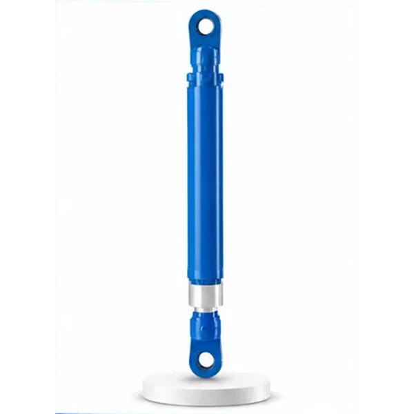
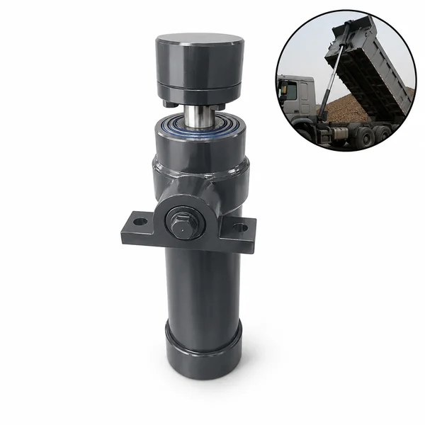
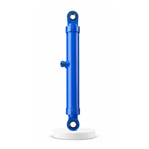
Hydraulic Press Cushion Cylinder

The Cylinder That
Pushes Back
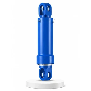
Every other press cylinder creates motion — pushes down, lifts up, shifts sideways, grips, tilts. The cushion cylinder is the only one that resists motion. Mounted below the die, it provides a controlled counter-force that opposes the ram — absorbing shock, preventing workpiece distortion, and controlling material flow during deep drawing and forming operations.
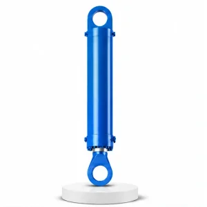
Not Force — Counter-Force
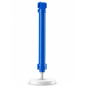
The cushion cylinder sits below the lower die or blank holder plate, rod pointing upward. When the master cylinder drives the ram down, the cushion cylinder does not get out of the way — it pushes back. The ram must overcome both the workpiece's forming resistance and the cushion cylinder's counter-force to complete the press stroke. This counter-force is the key to controlled forming.
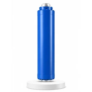
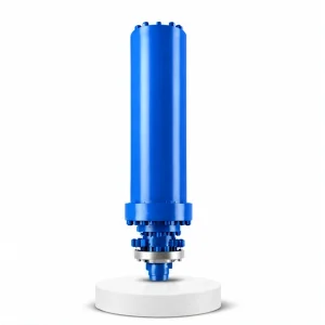
In deep drawing — the process of forming a flat sheet into a cup, can, panel, or housing — the cushion cylinder provides the blank holder force that pins the sheet edges against the die face while the punch draws the centre downward. Without cushion force, the sheet edges pull inward uncontrolled and wrinkle. With too much cushion force, the sheet cannot flow into the die and tears. The cushion cylinder maintains the precise force window between wrinkling and tearing — the narrow band where a successful draw lives. Korea Ever-Power manufactures cushion cylinders as part of the industrial engineering hydraulic cylinder programme.
Technical Specifications
| Parameter | Value |
|---|---|
| Product | Hydraulic Press Cushion Cylinder |
| Function | Absorb forging displacement / shock vibration |
| Bore Diameter | 75 mm – 300 mm |
| Rod Diameter | 50 mm – 180 mm |
| Stroke | ≤ 500 mm |
| Maximum Thrust | 1,130 KN (bore 300 mm / pressure 25 MPa) |
| Working Pressure | Up to 25 MPa |
| Certification | ISO 9001 · 100% hydrostatic tested |
The Wrinkle-Tear Window — Where the Cushion Cylinder Lives
In deep drawing, the cushion cylinder's blank holder force must fall within a narrow range. This range — the forming window — is bounded by two failure modes:
The sheet edges lift off the die face and buckle inward as the punch draws the centre down. Compressive hoop stress in the flange region exceeds the material's buckling resistance. The result is a wrinkled flange that cannot be flattened and must be scrapped. Wrinkling occurs when the blank holder force is insufficient to keep the sheet flat against the die face.
The sheet edges are pinned so tightly that the material cannot flow inward to feed the draw. The tensile stress at the punch radius exceeds the material's ultimate strength, and the part tears — typically at the bottom corner where the punch meets the cup wall. Tearing occurs when the blank holder force prevents the necessary material flow into the die cavity.
The cushion cylinder's job: maintain the blank holder force precisely between these two limits — throughout the entire draw stroke — even as the material properties change (work hardening, thickness thinning, friction variation). This requires proportional pressure control with feedback, not a fixed pressure setting.
Two Operating Modes — Drawing Cushion vs Forging Shock Absorber
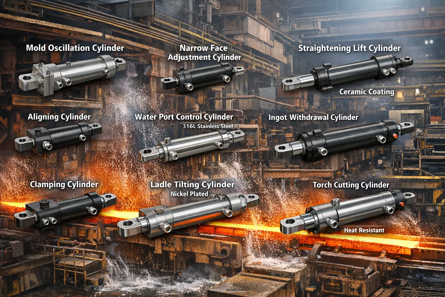
The cushion cylinder serves two different applications depending on the press type — and the engineering requirements differ significantly between them.
Drawing cushion (stamping/forming presses): The cushion provides a precisely controlled, variable-pressure counter-force that holds the blank edge while the punch draws the centre. The cushion force profile is typically programmed to vary during the stroke — higher at the start (to prevent initial wrinkling), gradually decreasing as the draw progresses and the material work-hardens (to prevent tearing). This is a slow, controlled, energy-absorbing operation.
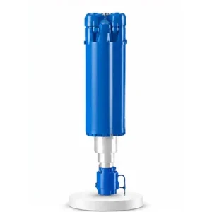
Shock absorber (forging presses): The cushion absorbs the impact energy when the ram hits the workpiece at the end of the press stroke. In free forging, the ram deceleration at workpiece contact sends a shock pulse through the press frame — the cushion cylinder below the lower die absorbs some of this energy, reducing the peak shock load on the foundation and the press structure. This is a rapid, high-energy, transient event — the opposite of the slow, controlled draw cushion.
The same cylinder hardware can serve both functions — the difference is in the hydraulic circuit: proportional pressure control for drawing, energy-absorbing orifice for shock absorption. Korea Ever-Power specifies the valve arrangement based on the application.
500 mm Stroke — The Shortest in the Press Cylinder Range
The cushion stroke matches the draw depth or the forging displacement — not the ram travel. The ram may travel 3,000–4,500 mm, but the cushion only compresses during the final 50–500 mm of that stroke — the forming phase. The approach phase (ram descending through air) does not engage the cushion at all.
Draw depth of 50–300 mm is typical for automotive panels and appliance housings. The cushion stroke matches this depth — the cylinder compresses exactly as far as the punch draws. Deeper draws (cups, canisters) may use up to 500 mm cushion stroke.
The forging displacement — the amount the workpiece compresses during a single press stroke — is typically 20–200 mm. The cushion stroke matches this displacement plus a margin for overtravel. The shock pulse duration is 10–50 milliseconds — far shorter than a drawing stroke.
Master cylinder: ≤4,500 mm. Mobile workbench: ≤7,500 mm. Lateral shift: ≤5,500 mm. Return cylinder: ≤4,500 mm. Cushion cylinder: ≤500 mm. The cushion needs only as much stroke as the forming or shock event requires — nothing more. More stroke would add cost and weight without benefit.
Maintenance — Cushion Cylinders Wear Differently
The cushion cylinder's wear pattern is unique among press cylinders because it operates in a short-stroke, high-frequency, energy-absorbing mode. The seals cycle over only 50–500 mm of bore surface — meaning the same narrow band of bore is swept by the piston seals on every stroke. This concentrated wear zone can develop a polish ring or a micro-roughness change that the rest of the bore does not experience.
On forging press shock absorbers, the energy absorption generates heat in the hydraulic fluid trapped inside the cylinder. Each shock pulse compresses the fluid and heats it — and because the cushion cylinder cycles frequently (every press stroke), the fluid temperature inside the cylinder can rise 20–40 °C above the bulk system temperature. This localised heating accelerates seal ageing in the cushion cylinder faster than in other press cylinders operating at the same system temperature.
Korea Ever-Power recommends inspecting cushion cylinder seals at half the interval used for master cylinder seals — typically every 1,000–2,000 operating hours. The seal kit includes the piston seal, rod seal, wiper, and all O-rings. Field changeout without removing the cylinder from the press is standard — the rod-end gland is designed for in-situ removal. Contact the hydraulic cylinder maintenance team for cushion-specific seal kit orders.
OEM & ODM
FAQ
Related Categories
Aanvullende informatie
| Editor |
|---|
Gerelateerde producten
-
Injection Molding Machine Mold Opening and Closing Cylinder
-
Hydraulic Press Mobile Workbench Cylinder
-
Filter Press Hydraulic Cylinder
-
Hydraulic Press Clamping Cylinder
-
Electric Furnace Cover Lifting Cylinder
-
Electric Furnace Cover Rotating Cylinder
-
Hydraulic Press Leveling Cylinder
-
Hydraulic Press Master Cylinder


