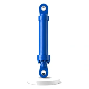
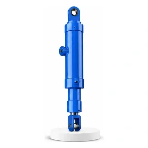
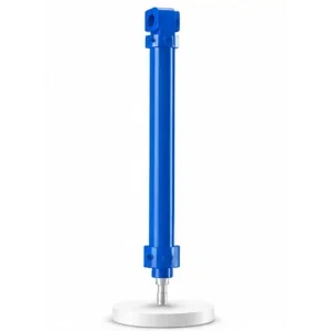
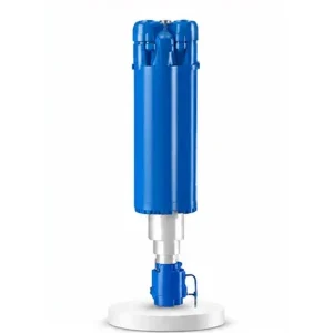
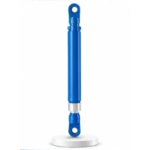
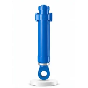
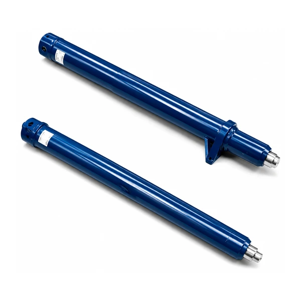
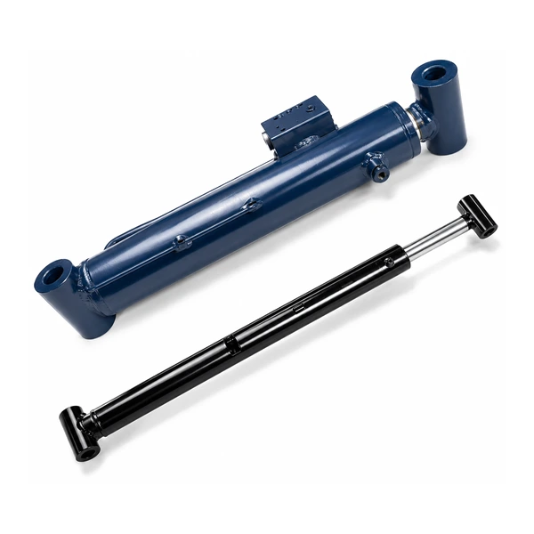
Injection Molding Machine Ejection Cylinder

Ejection Cylinder
The Last 600 mm
That the Customer Sees
The shooting cylinder docks. The injection ram fills the mould. The plastic cools. The mould opens. And then the ejection cylinder pushes the finished part out — the only cylinder in the injection moulding machine whose performance is directly visible on the product itself. Every ejector pin mark on a phone case, every warped edge on a dashboard panel, and every stuck part that halts the production line is a consequence of how this cylinder delivers its 600 mm of stroke.
How Ejection Works — One Cylinder, Many Pins, One Chance
After the mould opens, the plastic part remains stuck in the mould cavity — held in place by friction, vacuum suction, and the part's slight contraction around cavity features. The ejection cylinder pushes a steel ejector plate mounted behind the mould cavity. The ejector plate carries 4–50 ejector pins (depending on part size and complexity), each positioned to contact the plastic part at a specific point. When the cylinder extends, all pins advance simultaneously through holes in the cavity face, pushing the part out of the cavity and clear of the mould.
The ejection stroke is the only moment in the entire injection moulding cycle when a mechanical component physically pushes against the finished product. Every other phase (injection, packing, cooling) involves liquid or heat transfer — only ejection involves direct mechanical force on the solidified part. If the force is wrong, the speed is wrong, or the timing is wrong, the part is damaged. Korea Ever-Power manufactures ejection cylinders as part of the injection moulding machine cylinder family.

Technical Specifications
| Parameter | Value |
|---|---|
| Product | Injection Molding Machine Ejection Cylinder |
| Function | Eject the moulded product via ejector plate and pins |
| Bore Diameter | 90 mm – 220 mm |
| Rod Diameter | 50 mm – 140 mm |
| Stroke | ≤ 600 mm |
| Maximum Thrust | 760 KN (bore 220 mm / pressure 10 MPa) |
| Working Pressure | Up to 10 MPa (lowest in family — by design) |
| Certification | ISO 9001 · 100% hydrostatic tested |
10 MPa — Why the Lowest Pressure Protects the Product
The shooting cylinder (#24) operates at 25 MPa. The mold opening cylinder operates at similar pressures. But the ejection cylinder uses only 10 MPa — by design, not by limitation. The reason is the product itself.
At the moment of ejection, the plastic part has just solidified — it is cool enough to hold its shape but still warm enough to be pliable. Excess ejection force at this stage pushes the ejector pins into the warm plastic, leaving visible dents (ejector pin marks) or, in severe cases, punching through thin wall sections. On cosmetic surfaces (visible faces of consumer products), pin marks are a reject-level defect. On structural parts, excessive ejection force can distort ribs, bosses, or snap-fit features while they are still below full strength.
The large bore (90–220 mm) at low pressure (10 MPa) provides ample force capacity (up to 760 KN) while keeping the system pressure low enough that the machine operator's pressure adjustment has fine resolution — small pressure changes produce small force changes, giving precise control over the ejection force applied to delicate parts.
Three-Phase Ejection Speed — Break, Clear, Decelerate
The ejection stroke is not a single-speed push. The optimal ejection uses three distinct speed phases — each serving a different purpose and requiring different cylinder behaviour:
The part is stuck to the cavity wall by friction, vacuum, and contraction. The initial push must break all adhesion points simultaneously — which requires high force at very low speed. A fast start tears the part at the weakest adhesion point instead of releasing it uniformly, causing warpage. The cylinder must deliver maximum force at minimum velocity — slow, steady, even pressure build-up.
Once the part is free from the cavity, the pins push it out rapidly — the faster, the better for cycle time. The part is no longer touching the cavity walls, so force is minimal (just the weight of the part and the friction of the ejector pins in their guide holes). This phase is speed-limited, not force-limited.
The ejector plate must stop smoothly at the end of stroke — not slam into the mechanical stop. Hard impact at the end of every ejection stroke (thousands per day) fatigues the ejector plate, the return pins, and the cylinder cushion. Korea Ever-Power calibrates the end-of-stroke cushion for the specific ejector plate mass and ejection speed.
This three-phase speed profile is achieved through the machine's proportional valve — the ejection cylinder must respond smoothly to the valve's flow commands across the full speed range, from the slow break-free crawl to the fast clearing sweep. Contact the hydraulic cylinder engineering team for ejection speed profile specifications.
Four Ways Ejection Fails — And What the Cylinder Can Prevent
Visible dents or shiny spots where the ejector pins contacted the part. Caused by: excessive ejection force, insufficient cooling time (part too soft at ejection), or pins with too-small contact area. The cylinder's adjustable pressure setting lets the operator reduce ejection force to the minimum needed — eliminating pin marks without risking sticking.
The part bends or twists during ejection because the ejection force is applied unevenly — some pins push harder than others due to unequal friction on different parts of the cavity. The ejection cylinder must deliver uniform force to all points of the ejector plate simultaneously — which requires a centred rod connection and a rigid plate to distribute the force evenly to all pins.
The part does not release from the cavity — the ejection force is insufficient to overcome adhesion, vacuum, or undercut interference. The machine alarms and stops. An operator must manually remove the stuck part. Each stuck-part event costs 1–5 minutes of production time. The cylinder must provide enough force reserve to handle the occasional difficult ejection without operating at maximum force (which would cause pin marks on normal parts).
If the injection was incomplete (a "short shot"), the partially filled part has thin, weak sections that break during ejection — leaving fragments inside the mould that block the next cycle. The cylinder's slow break-free phase helps detect stuck fragments (unusual resistance during the initial push triggers an alarm) before the fast phase drives a broken part into the cavity.
Manufacturing
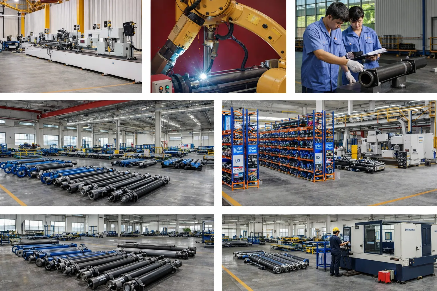
The ejection cylinder's bore (90–220 mm) is honed to Ra 0.2–0.4 µm — the Korea Ever-Power standard for consistent, low-friction motion. The rod is chrome plated at 30–50 µm (clean environment specification). Seals are standard NBR or polyurethane selected for low breakaway friction — the slow break-free phase demands that the cylinder starts moving smoothly at very low speed without stiction (stick-slip). The end-of-stroke cushion is calibrated for the ejector plate mass and maximum ejection speed. Every ejection cylinder is hydrostatic tested at 1.5× working pressure (15 MPa) and functionally tested for smooth low-speed start and full-speed extend with cushion deceleration verification.
OEM & ODM
FAQ
Related Categories
Додатне информације
| Editor |
|---|