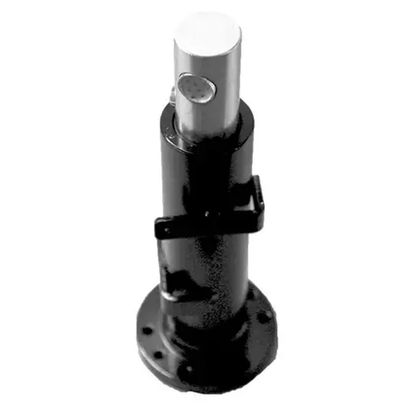
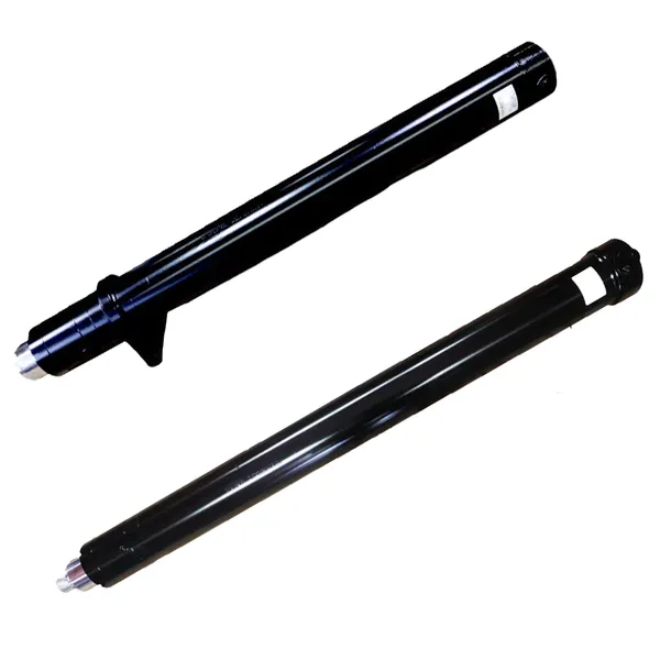
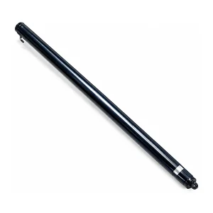
Forklift Lifting Hydraulic Cylinder — Single-Acting Mast Lift Cylinder

Forklift Lifting Hydraulic Cylinder
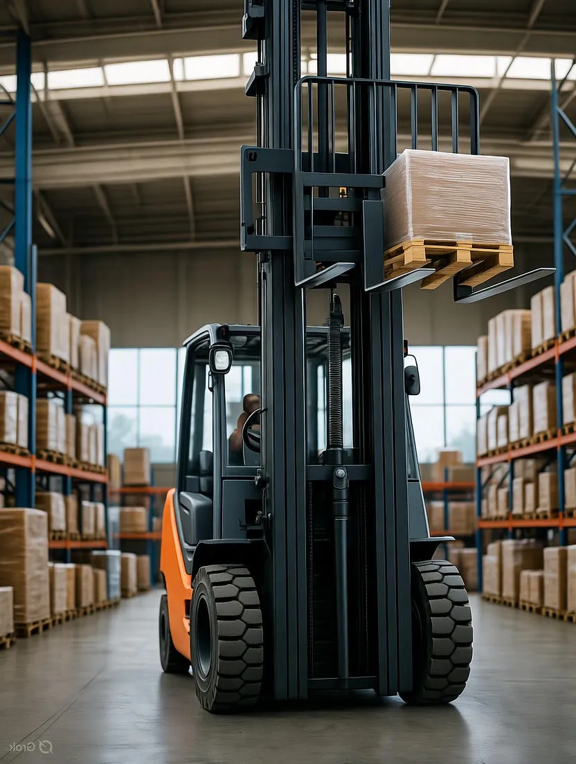
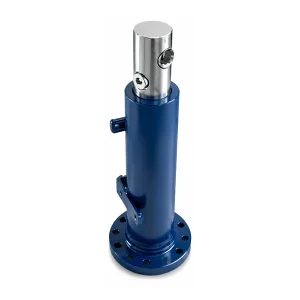
The cylinder that carries the load. Every kilogram lifted by a forklift passes through this single-acting hydraulic cylinder — from ground level to maximum stack height. Rated at 18.1 MPa with a 1,500 mm full stroke, it provides the controlled vertical force that raises the mast carriage, forks, and payload in a single smooth motion. When the operator lowers the forks, the control valve meters the return oil flow to provide a controlled descent speed regardless of load weight.
Why Forklift Lift Cylinders Are Single-Acting — Not Double-Acting
A question that mechanical engineers outside the forklift industry frequently ask: why is the lift cylinder single-acting when the tilt cylinder on the same machine is double-acting? The answer involves both physics and safety.
The lift cylinder only needs hydraulic force in one direction — upward. Gravity provides the return force for free. The combined weight of the carriage, forks, and payload creates a constant downward force that retracts the piston rod when the control valve opens the return path. A double-acting lift cylinder would add weight, cost, and a second hydraulic hose run up the mast for no functional benefit — the load always wants to come down.
The safety benefit is equally important. In a single-acting system, the only way the forks can descend is through a metered flow path back to the hydraulic tank. If a hose bursts on the pressure side, the forks stay at their current height — the load weight pushes against the check valve in the circuit, which blocks flow in the return direction. This fail-safe characteristic is why every forklift hydraulic cylinder used for vertical lifting is single-acting: a hose failure causes a stop, not a drop.
Extend (Lift)
Hydraulic pressure pushes piston upward. Oil flows from pump → directional valve → cylinder bore port. Full bore area generates lift force.
Retract (Lower)
Load weight pushes piston down. Oil returns through metered flow control valve → tank. Descent speed is independent of load weight.
Hold (Stationary)
Check valve blocks return flow. Load weight cannot force oil out of cylinder. Forks hold position indefinitely without pump pressure.
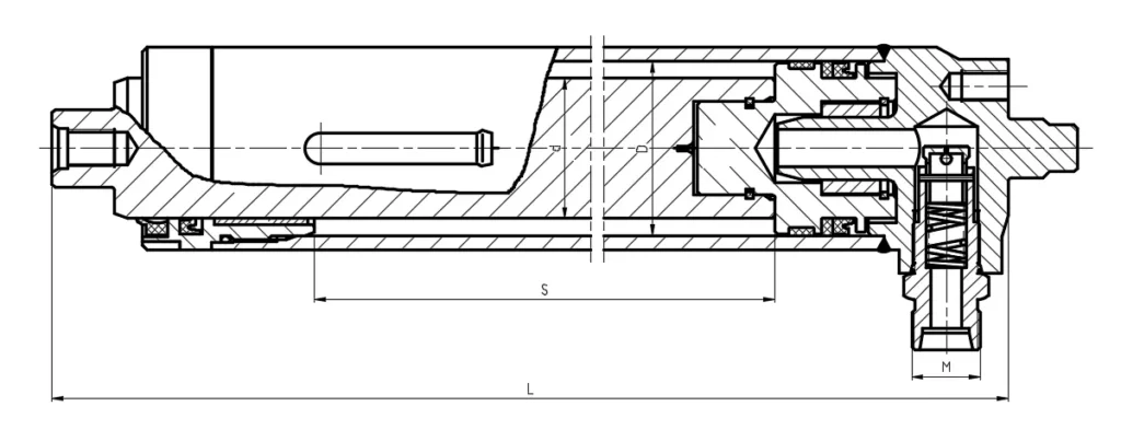
Complete Dimensional Specifications — All 5 Models
Five lifting cylinder models serve the 1.5–3.5 tonne counterbalance forklift range. The two bore diameters (Φ56 and Φ60) correspond to two load capacity classes, while the different installation distances (1,658 to 1,808 mm) accommodate different mast frame geometries. Two hydraulic port thread standards are available — G1/2 BSP for forklifts originally equipped with BSP hydraulic fittings, and M22×1.5 metric for metric-standard systems.
| Drawing Number | Bore (D) | Rod (d) | Stroke (S) | Install Dist (L) | Pressure | Ports (M) | Weight |
|---|---|---|---|---|---|---|---|
| N30M300-5/400000-000 | Φ56 | Φ45 | 1500 | 1658 | 18.1 MPa | G1/2 | 32.6 kg |
| A2A30M300-400000-000 | Φ56 | Φ45 | 1500 | 1658 | 18.1 MPa | M22×1.5 | 36 kg |
| 3.5N4.5H-400000-003 | Φ60 | Φ45 | 1505 | 1780 | 17.5 MPa | M22×1.5 | 41 kg |
| N35M300-5/400000-001A | Φ60 | Φ45 | 1500 | 1808 | 18.1 MPa | G1/2 | 46 kg |
| A2A35M300-400000-000 | Φ60 | Φ45 | 1500 | 1808 | 18.1 MPa | M22×1.5 | 50 kg |
All dimensions in mm. Installation distance (L) measured at full retraction, pin centre to mounting face. Stroke tolerance ±2 mm. Weights are dry. The Φ56 bore models (N30M, A2A30M) share a common mast channel width; the Φ60 bore models (3.5N, N35M, A2A35M) require the wider channel found on 3.0–3.5 tonne mast frames.
Lift Force Output — What the Numbers Mean for Your Load Capacity
The lift force produced by the cylinder is not the same as the forklift's rated load capacity — it is substantially higher. The cylinder must lift not only the payload but also the weight of the carriage, forks, mast inner channel, chains, and hoses. On a typical 3-tonne counterbalance forklift, the dead weight of the mast assembly above the cylinder is approximately 300–500 kg. The cylinder force must exceed the sum of the payload and the dead weight to produce upward acceleration.
| Bore | Piston Area (cm²) | Force at 18.1 MPa (kN) | Equivalent Lift Mass (kg) | Typical Forklift Class |
|---|---|---|---|---|
| Φ56 | 24.63 | 44.6 | 4,546 | 1.5–2.5 t |
| Φ60 | 28.27 | 51.2 | 5,219 | 3.0–3.5 t |
Force = pressure × area. Equivalent lift mass = force ÷ 9.81 m/s². These values represent maximum static force at the cylinder rod. The actual rated load capacity of the forklift is lower because it accounts for mast dead weight, chain pulley losses (typically 3–5%), and the required acceleration margin for a responsive lift response. The 3.5N4.5H model at 17.5 MPa produces 49.5 kN (5,042 kg equivalent).
Understanding Free Lift, Primary Lift, and Secondary Lift
The lifting cylinder with its 1,500 mm stroke is part of a chain-and-pulley system that multiplies the cylinder stroke into total fork travel. How this multiplication works depends on the mast type — and understanding the mast type is essential for selecting the correct cylinder replacement.
Two-Stage (Simplex) Mast
The lift cylinder extends and simultaneously raises the inner mast channel through a chain-and-sheave system. The fork travel is approximately equal to the cylinder stroke (1:1 ratio). With the 1,500 mm stroke cylinder, maximum lift height is approximately 1,500 mm above the mast collapsed height. No free lift — the mast begins extending as soon as the forks leave the ground.
Triple-Stage (Triplex) Mast
The cylinder first extends through a free-lift phase — the forks rise inside the collapsed mast channels without increasing the overall mast height. After the free lift is exhausted, the cylinder continues extending and raises the intermediate and outer mast channels through a 2:1 chain multiplication. With the 1,500 mm stroke, total fork travel can reach 3,000–4,500 mm depending on chain routing.
Full Free Lift (FFL) Mast
Uses a separate short free-lift cylinder (in addition to the main lift cylinder) that raises the forks to the full height of the collapsed mast before the main lifting cylinder begins extending. This configuration is standard for container-entry forklifts that must enter standard shipping containers (2,591 mm internal height) with the mast collapsed. The main lifting cylinder specification remains the same.
When replacing the lifting cylinder, always verify whether your mast uses a separate free-lift cylinder. If it does, the main lift cylinder installation distance will be different from a non-FFL mast of the same forklift model. Measure the installation distance (L) on the existing cylinder before ordering — do not rely on the forklift model number alone.
Built for 10,000+ Hours — Construction and Material Specification
| Cylinder Tube Material | Seamless cold-drawn steel tube, DIN 2391 / EN 10305-1 |
| Bore Finish | Precision honed, Ra 0.2–0.4 μm |
| Piston Rod Material | SAE 1045 / C45 medium carbon steel, induction hardened |
| Rod Surface Treatment | Hard chrome plated, 20–30 μm thickness, Ra ≤ 0.2 μm |
| Piston Seal | NBR compound, single-lip design for single-acting operation |
| Rod Seal | Polyurethane U-ring + PTFE wear ring |
| Dust Wiper | Double-lip design, metal-reinforced |
| Proof Test Pressure | 27 MPa (1.5× working pressure) |
| External Finish | E-coat primer + polyurethane topcoat, salt spray 500+ hours |
Load Drift Test — The Critical Quality Check for Lift Cylinders
The single most important performance parameter for a forklift lifting hydraulic cylinder is not its lift force or its speed — it is its drift rate. Drift is the slow, unintended descent of the forks when the control valve is in the neutral (hold) position. A small amount of drift is normal due to thermal contraction of the hydraulic oil as it cools, but excessive drift indicates internal seal bypass or a leaking check valve.
Lift Cylinder Working Environments
High-Throughput Warehousing
Multi-shift distribution centres running 16–24 hours per day accumulate 2,500–4,000 full lift cycles per week. At this rate, the lifting cylinder completes over 200,000 full-stroke cycles in a single year. The combination of precision bore honing and chrome rod plating used in these hydraulic cylinders is specifically designed for this sustained cycle count, maintaining the ≤ 25 mm drift specification through the full 3–5 year seal replacement interval.
Lumber Yards and Outdoor Storage
Outdoor forklifts handling lumber, steel stock, and building materials operate in rain, dust, and temperature extremes. The double-lip metal-reinforced dust wiper prevents abrasive contaminant ingress that would score the rod surface and destroy the rod seal within months. The E-coat plus polyurethane external finish provides corrosion protection that withstands 500+ hours of salt spray testing — far exceeding the requirements of inland operations.
Food and Beverage — Clean Environments
Food-grade warehouses subject forklifts to regular washdown procedures using alkaline cleaning agents. The seal materials used in the lifting cylinder — polyurethane rod seal and NBR piston seal — are resistant to the pH 9–11 cleaning solutions commonly used in food processing environments. The zero external leakage specification ensures that no hydraulic oil contaminates the product handling area, supporting HACCP and food safety compliance.
Inspection and Maintenance Schedule for Lift Cylinders
| Interval | Inspection Item | Action Threshold |
|---|---|---|
| Daily (pre-shift) | Visual check for oil weep at rod seal area | Any visible oil film on rod → schedule seal replacement |
| Weekly | Fork drift test: raise forks to max height with rated load, hold 10 min, measure descent | Drift > 50 mm in 10 min → remove cylinder for seal inspection |
| 500 hours | Inspect rod surface for scoring, pitting, chrome damage | Scratches visible/tangible with fingernail → schedule re-chrome or rod replacement |
| 2,000 hours | Check cylinder mounting hardware, pivot pins, chain anchor bolts | Any radial play in pivot > 0.5 mm → replace pin/bush |
| 5,000–8,000 hours | Full cylinder reseal (planned preventive replacement) | Replace complete seal kit regardless of condition |
Forklift Lifting Hydraulic Cylinder — Technical Questions
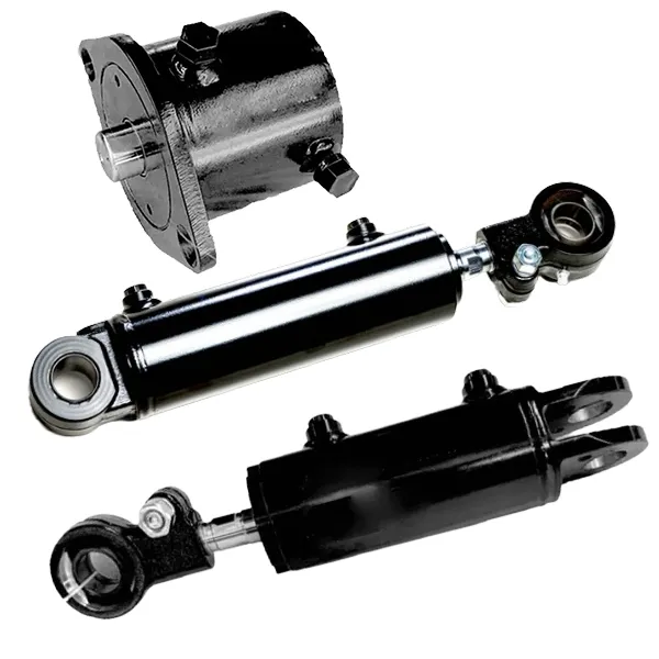
Other Cylinders on the Same Forklift
其他信息
| Editor | Cxm |
|---|
相关产品
-
Pallet Truck Lift Cylinder | Bore Φ40–45mm | Ultra-Compact
-
Forklift Tilt Cylinder | EP-HCYY11112001 Model
-
Forklift Truck Lift Oil Cylinder — Single-Acting Hydraulic Lift Cylinder
-
Industrial Vehicle Short Stroke Forklift Lift Cylinder
-
Custom Hydraulic Lift Cylinder — OEM Lift Cylinder with Integrated Check Valve and Sprocket for Forklifts
-
Tractor & Forklift Hydraulic Steering Cylinder — OEM Cross-Industry Power Steering Cylinder
-
OEM Double Acting Forklift Hydraulic Cylinder
-
Lift Hydraulic Cylinder for Cart — Pallet Truck Lift Cylinder


