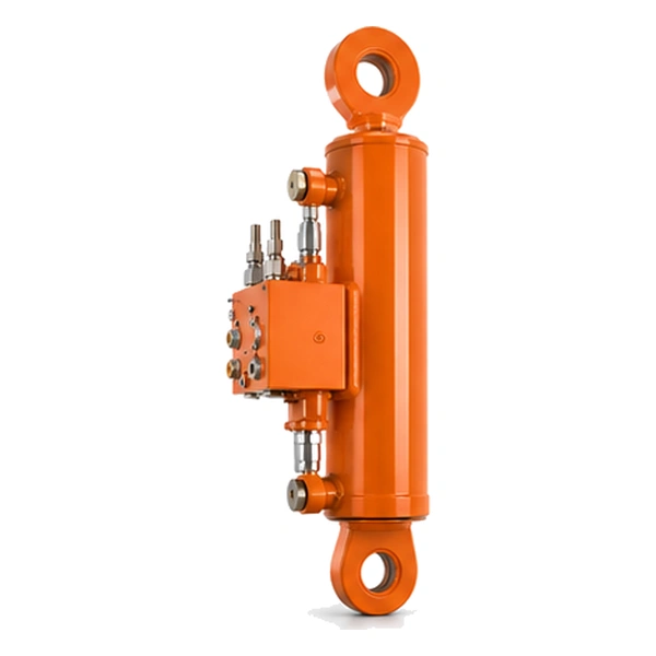
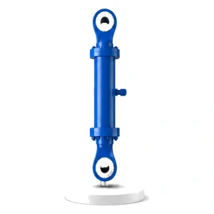
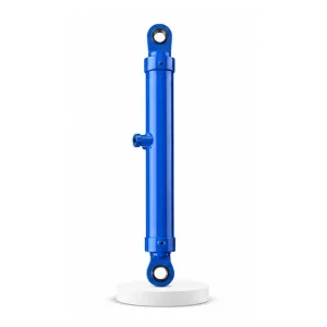
Special Oil Cylinder For Turnover Plow

Turnover Plow · Flip Cylinder
Flip 2 Tonnes.
180 Degrees.
Every Single Pass.
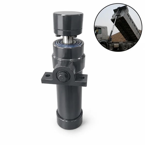
The tractor cylinder (#35) lifts, steers, and loads. This cylinder does something none of those do — it rotates an entire plough frame 180° at the headland, slamming 500–3,000 kg of steel and soil from one side to the other in under 8 seconds. No other agricultural cylinder combines this much rotational force, this much impact, and this much exposure to soil and stone — every pass, hundreds of times per ploughing day.
Why a Plough Needs to Flip — The Dead Furrow Problem
A conventional plough throws soil to one side only — typically to the right. The tractor drives up the field, turns at the headland, and drives back. But on the return pass, the plough still throws soil to the right — which is now the opposite direction relative to the field. This creates "dead furrows" (open trenches) and "back furrows" (raised ridges) across the field, leaving an uneven surface that interferes with seeding, irrigation, and crop establishment.
The turnover (reversible) plough solves this: it carries two mirror-image sets of mouldboards — one set for each direction. At the headland, the cylinder rotates the entire frame 180°, presenting the opposite set of mouldboards. The soil is now thrown in the same direction relative to the field on both passes — producing a flat, uniform surface with no dead furrows. The result: better seedbed preparation, more uniform crop emergence, and easier irrigation management. Korea Ever-Power manufactures the turnover cylinder as part of the agricultural and industrial cylinder range.
The Headland Flip — Four Seconds of Maximum Demand
At the end of every pass, the tractor reaches the headland. The operator lifts the plough out of the ground, and the turnover cylinder executes the flip:
The tractor's 3-point hitch cylinders (#35) raise the plough until all mouldboards are above ground level. The plough hangs from the hitch — free to rotate.
The cylinder pushes a lever arm on the plough's turnover shaft. The entire plough frame — mouldboards, shares, frame tubes, and accumulated soil — begins to rotate around the horizontal axis. This is the maximum force phase: the cylinder must overcome the dead weight of the plough at the worst-case lever arm angle (typically 90° from horizontal, where gravitational torque is maximum).
Once the plough rotates past the vertical (top-dead-centre), gravity accelerates it toward the opposite side. The cylinder must now decelerate — switching from driving the rotation to braking it. Without braking, the 2-tonne plough slams into the mechanical stop at full speed.
The cylinder's end-of-stroke cushion (or meter-out circuit) decelerates the plough over the last 15–30° of rotation, bringing the mass to a controlled stop on the mechanical support stops. The opposite mouldboard set is now in the working position. The operator lowers the plough into the soil and begins the return pass. Contact the hydraulic cylinder engineering team for turnover cylinder specifications.
Rotational Force — Why the Turnover Cylinder Is Sized for the Worst 5 Degrees
The turnover cylinder does not produce a constant force through its stroke — the load varies dramatically with the plough's rotation angle. At the start of the flip (plough lying on one side), the gravitational torque is low — the plough's centre of gravity is close to the rotation axis. As the plough rotates toward vertical, the torque increases — the centre of gravity moves further from the axis. At exactly 90° (plough standing vertical), the gravitational torque is maximum.
The cylinder must deliver enough force at this worst-case 90° position to keep the plough rotating — against the full gravitational torque of 500–3,000 kg at the maximum lever arm distance. On a 5-furrow reversible plough weighing 2,000 kg with the centre of gravity 400 mm from the rotation axis, the required cylinder force at 90° is approximately 40–60 KN (depending on the cylinder's own lever arm geometry).
After passing 90°, gravity helps — but the cylinder must now brake instead of push. The hydraulic circuit typically uses a counterbalance valve that restricts the return oil flow, preventing the plough from free-falling onto the opposite stops. The cylinder, valve, and mechanical stops must all be designed as a coordinated system.
The Hidden Load — Accumulated Soil, Stones, and Wet Clay
When the plough lifts out of the ground, soil clings to the mouldboards, shares, and frame. In wet clay conditions, this accumulated soil can add 500–1,500 kg to the plough's dry weight — increasing the cylinder's required flip force by 30–50% above the clean-plough calculation. The cylinder must be sized for the worst-case wet-soil condition, not the dry-weight specification.
Stones lodge between the mouldboard and the frame during ploughing. During the flip, a trapped stone can jam the rotation — creating a sudden force spike that the cylinder must absorb without stalling. The cylinder and the hydraulic relief valve must handle these intermittent jams without damage to the cylinder, the plough frame, or the tractor's hydraulic system.
Soil accumulation is not equal on both mouldboard sets — the set that was in the ground carries more soil than the set that was in the air. This asymmetry shifts the plough's centre of gravity off-centre, creating a rotational imbalance. The cylinder must handle this imbalance — which changes the top-dead-centre force requirement and the braking requirement on the falling side.
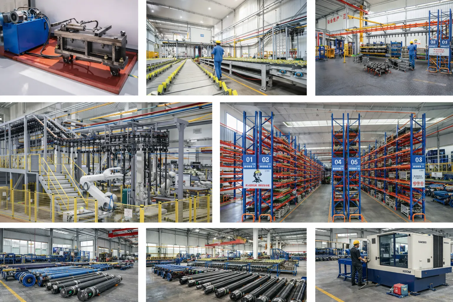
Manufacturing — Built for Rotational Impact, Not Linear Motion
Most hydraulic cylinders produce linear motion — push and pull along a straight line. The turnover cylinder produces linear motion at the rod but the load is rotational — the rod pushes a lever arm that rotates the plough. This creates side loads on the rod and piston that do not exist in purely linear applications. Korea Ever-Power specifies oversized rod guide bearings and a spherical rod end to accommodate the angular misalignment as the lever arm rotates through 180°.
The barrel end-of-stroke cushion is sized for the worst-case landing impact — the full plough mass accelerating under gravity for the last 15–30° of rotation. This is a much higher energy cushion than any linear application because the mass is accelerating rotationally, not just decelerating linearly. The cushion nose and the deceleration passage are designed for this specific energy absorption requirement.
The bore is honed to Ra 0.2–0.4 µm. Chrome plating is 80 µm (maximum — the rod is directly exposed to soil splash during ploughing). Double-lip wipers with a hardened scraper ring remove compacted soil from the rod before it enters the seal. Every turnover cylinder is hydrostatic tested at 1.5× working pressure and impact-tested — verifying cushion performance under a simulated plough-landing shock load.
OEM & ODM
FAQ
Related Categories
Additional information
| Editor |
|---|
Related products
-
Injection Molding Machine Mold Opening and Closing Cylinder
-
Cement Equipment Vertical Mill Cylinder
-
Injection Molding Machine Shooting Cylinder
-

Hydraulic Press Lateral Shift Anvil Cylinder
-
Injection Molding Machine Ejection Cylinder
-
Hydraulic Press Rear Side Shift Cylinder
-

Electric Furnace Lifting Cylinder
-
Electric Furnace Cover Rotating Cylinder


