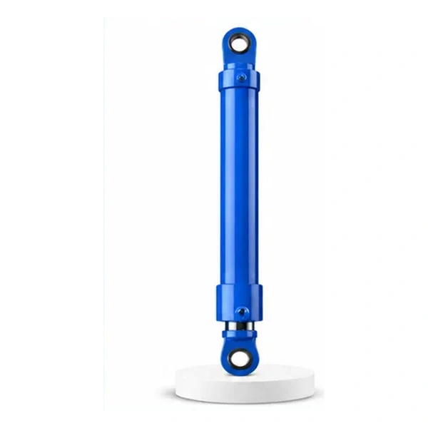
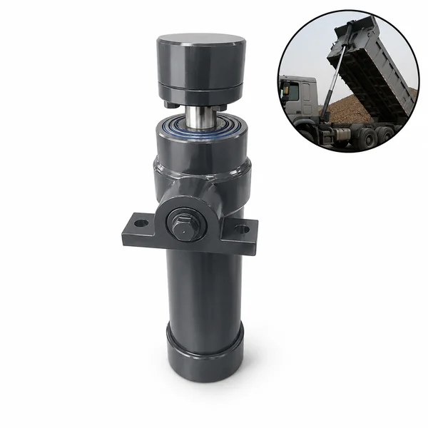
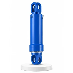
Electric Furnace Tipping Cylinder

Controlled Steel Pour
The Controlled Pour
of Liquid Steel
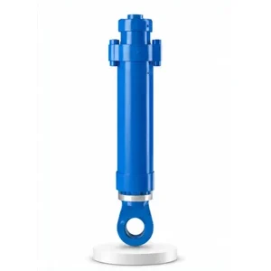
Every 40–70 minutes, the electric arc furnace completes a melt. The lock cylinder disengages. The tipping cylinder takes over — tilting the entire furnace body to pour 100–200 tonnes of liquid steel at 1,600 °C into the waiting ladle below. Too fast and the metal splashes. Too slow and the steel temperature drops below specification. The operator's hand is on the proportional valve; the tipping cylinder translates that command into the controlled rotation of a 500-tonne furnace.
Two Directions of Tilt — Steel Forward, Slag Backward
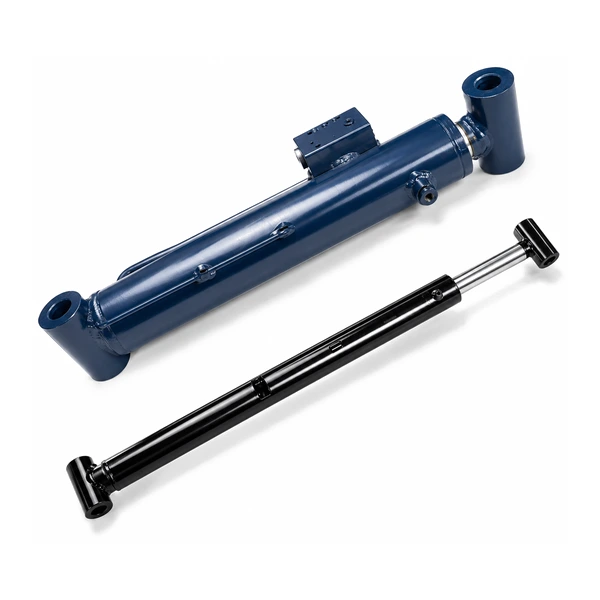
The electric furnace tilts in two opposite directions for two different purposes — and the tipping cylinder drives both movements from its position on the furnace tilt cradle.
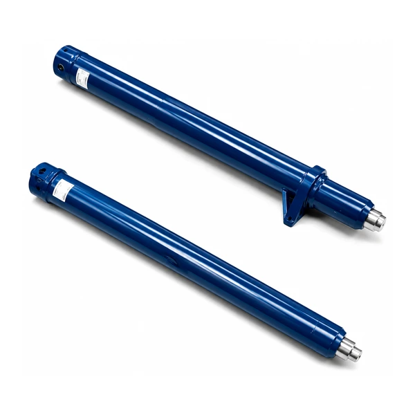
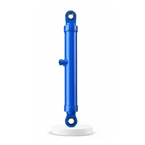
The tipping cylinder must produce thrust in both directions — extending to tilt forward, retracting to tilt backward (or vice versa, depending on the cylinder mounting geometry). This is why the cylinder is double-acting with full pressure capability on both ports. Korea Ever-Power engineers the cylinder and the tilt mechanism geometry together as part of the electric furnace cylinder family.
Technical Specifications
| Parameter | Value |
|---|---|
| Product | Electric Furnace Tipping Cylinder |
| Function | Tilt furnace for steel tapping and slag removal |
| Bore Diameter | 320 mm |
| Rod Diameter | 300 mm (93.8% of bore) |
| Working Pressure | 14 MPa |
| Maximum Thrust | 989 KN |
| Tilt Directions | Forward (steel tap, 40–45°) + Backward (slag, 10–15°) |
| Certification | ISO 9001 · 100% hydrostatic tested |
Tipping Speed Determines Steel Quality
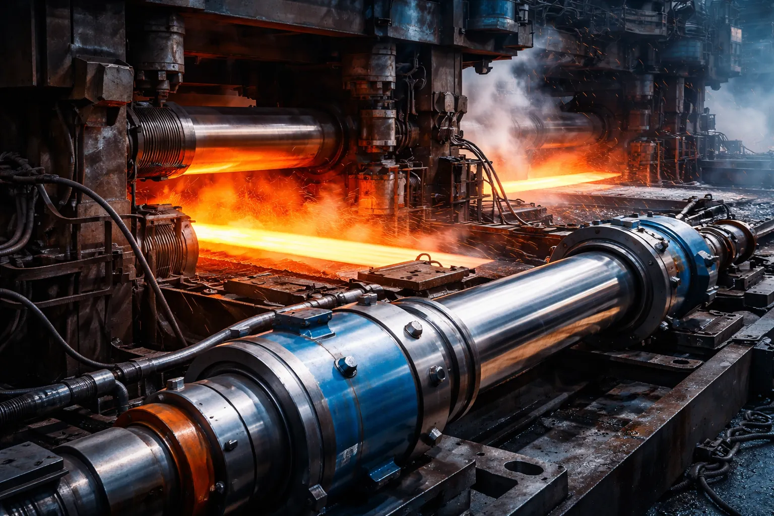
The tipping cylinder does not simply dump the metal — it controls the pour rate, which directly affects the quality of the steel reaching the ladle. This is why proportional speed control is essential, and why simple on/off hydraulic valves are never acceptable for tipping service.
Temperature loss during tapping. Every second of tapping time costs 1–3 °C of steel temperature. A 200-tonne tap that takes 5 minutes instead of 3 minutes loses an additional 120–360 °C of superheat — which may drop the steel below the minimum casting temperature, requiring reheating in the ladle furnace (energy waste, schedule delay).
Oxygen pickup during tapping. As the molten steel stream falls through air into the ladle, it absorbs oxygen — which must later be removed by adding expensive deoxidisers (aluminium, silicon). A fast, compact stream (steep tilt angle, high flow rate) exposes less surface area to air than a slow, thin stream (shallow tilt, low flow). The tipping cylinder's angle control directly affects the oxygen content of the tapped steel.
Slag carryover control. Near the end of tapping, the slag layer approaches the tapping spout. The operator must slow and then stop the tilt at precisely the right moment — pouring the last of the steel while keeping the slag inside the furnace. Tilting too far carries slag into the ladle (contaminating the steel); stopping too early leaves valuable steel in the furnace (yield loss). This final few degrees of tilt control is the most skill-dependent moment in EAF steelmaking — and the tipping cylinder must respond to the operator's command without lag, overshoot, or hesitation.
Engineering Insight — Why On/Off Valves Cannot Do This Job
A standard directional valve has three states: extend, retract, or stop. The tipping cylinder needs infinitely variable speed control — fast at the start of the tap (to minimise temperature loss), progressively slower as the furnace empties (to control the pour stream), and extremely precise in the final degrees (to separate steel from slag). This requires proportional hydraulics.
A proportional valve on the tipping cylinder circuit adjusts the flow to the cylinder continuously — from zero to maximum — in response to the operator's joystick or the automated tapping control system. The flow determines the tilt speed. The operator can tilt at 2°/second at the start and 0.1°/second at the end — a 20:1 speed range — from the same cylinder and the same valve.
As the furnace tilts forward, the centre of gravity of the molten metal shifts toward the tapping spout — creating a gravity moment that tries to accelerate the tilt. Without a counterbalance valve, the furnace would tip faster and faster as it tilts further — a runaway pour. The counterbalance valve on the rod side of the tipping cylinder provides a controlled back-pressure that prevents gravity-assisted runaway, ensuring the tilt speed follows the operator's command at all times.
An emergency stop command must lock the furnace at its current tilt angle — instantly, without drift. The tipping cylinder's circuit includes a pair of pilot-operated check valves that seal both ports when the proportional valve is de-energised, trapping the oil and freezing the cylinder's position. No coast, no creep, no additional tilt after the stop command. Contact the hydraulic cylinder engineering team for tipping control circuit specifications.
The Tapping Zone — Where the Cylinder Works
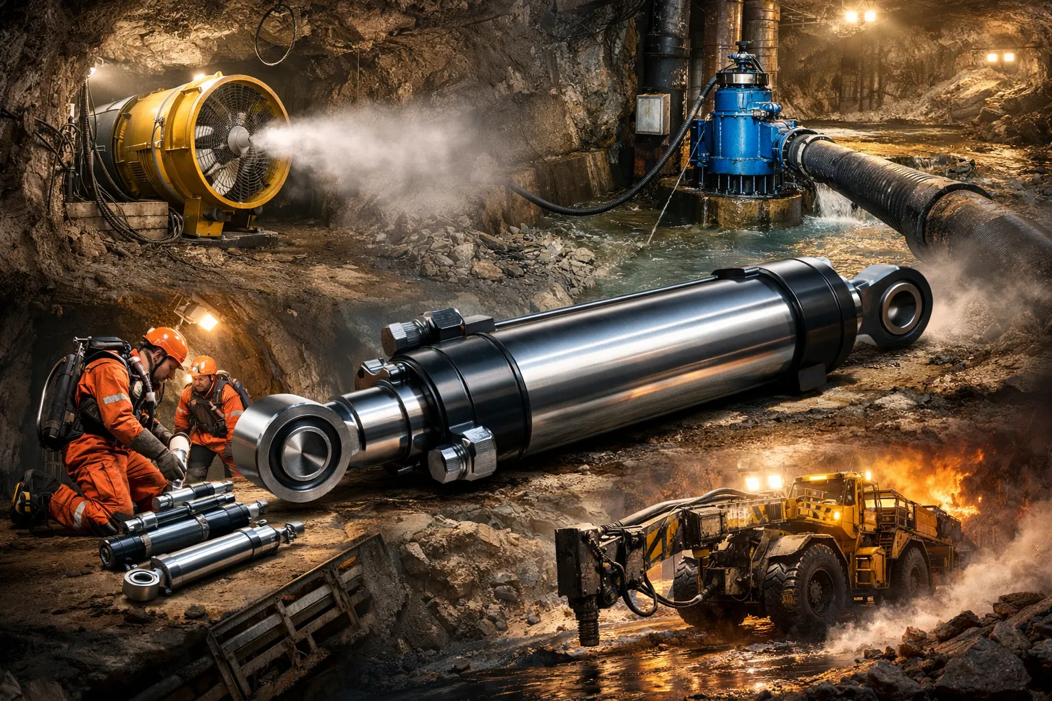
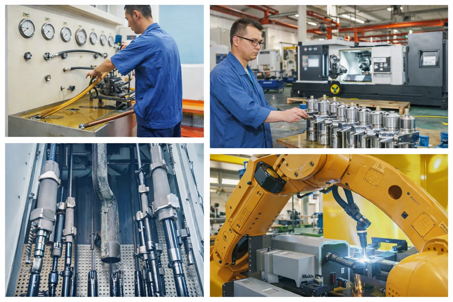
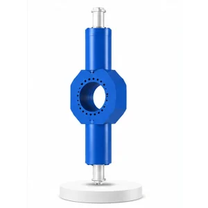
The tipping cylinder is mounted on the furnace tilt cradle — directly below the furnace shell, in the tapping zone. This is the most hostile location in the melt shop: radiant heat from the furnace shell above, splashing steel and slag during tapping, forge spray (the cooling water applied to the tapping spout), and accumulated scale and debris on the tilt platform.
The rod surface is particularly vulnerable. During tapping, molten metal droplets and slag particles can land on the exposed rod. A single steel splash that bonds to the chrome surface creates a raised point that scores the rod seal on the next stroke — initiating a leak that progressively worsens until seal replacement. Korea Ever-Power specifies a telescopic rod shroud or bellows boot as standard for tipping cylinders to prevent splash contact with the rod.
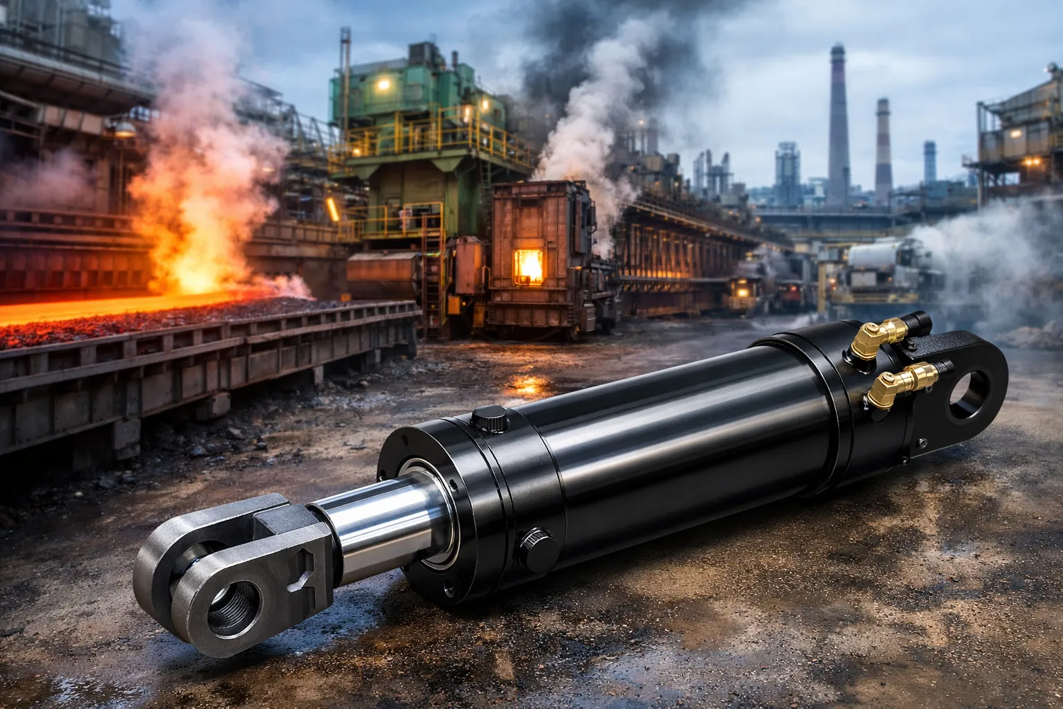
The same thermal protection features used on the cover lifting cylinder (#14) — heat shields, water-cooled barrel jacket (optional), FKM seals, and fire-resistant hydraulic fluid compatibility — apply to the tipping cylinder. The tipping cylinder's proximity to the tapping stream makes it even more splash-exposed than the cover lifting cylinder, which is mounted higher on the furnace support structure.
Manufacturing
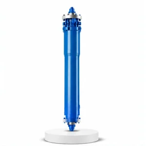
The 320 mm bore and 300 mm rod (93.8% ratio) share the same structural-column design philosophy as the cover lifting cylinder (#14) — the massive rod supports the furnace weight component that acts through the tilt mechanism. Korea Ever-Power machines the rod from forged steel bar, stress-relieves after rough machining, and chrome plates to 80–100 µm for splash resistance. The bore is honed to Ra 0.2–0.4 µm for consistent proportional control at low tilt speeds. The cylinder is hydrostatic tested at 1.5× working pressure (21 MPa) and functionally tested for proportional speed control across the full tilt range — verifying smooth, lag-free response to the proportional valve signal at all speeds from 0.1°/s to the maximum tilt rate.
OEM & ODM
FAQ
Related Categories
معلومات إضافية
| Editor |
|---|
منتجات ذات صلة
-
Pressurized Hydraulic Cylinder for Vulcanizing Machine
-
Cement Equipment Roller Press Cylinder
-
Electric Furnace Cover Lifting Cylinder
-
Electric Furnace Lifting Cylinder
-
Hydraulic Press Rear Side Shift Cylinder
-
Electric Furnace Cover Rotating Cylinder
-
Hydraulic Press Return Cylinder
-
Hydraulic Press Tilt Cylinder


