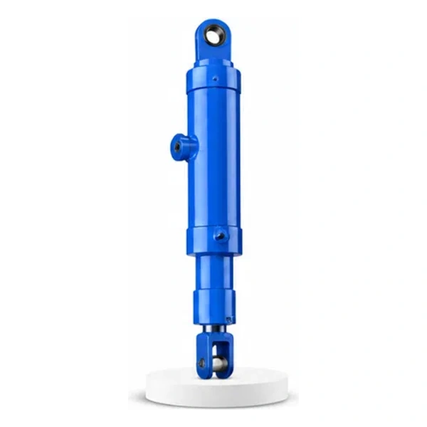
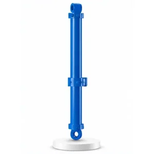
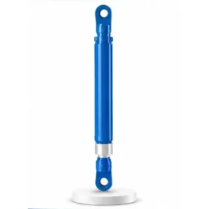
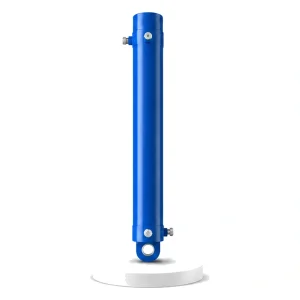
Electric Furnace Lock Cylinder

Safety-Critical
17 KN of Force.
100+ Tonnes of Molten
Steel Held in Place.
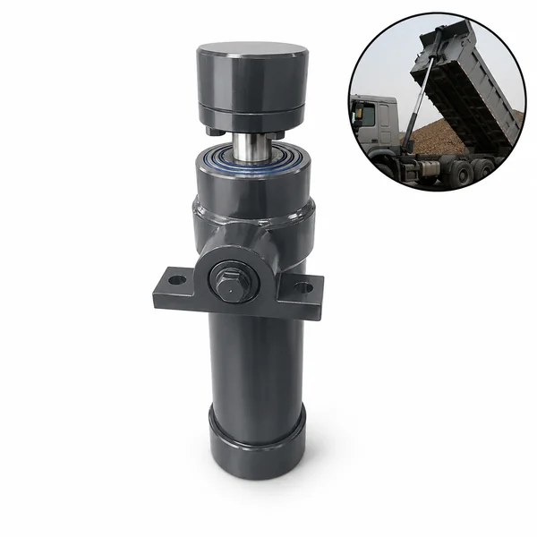
The smallest bore in the catalogue — 40 mm. The lowest thrust — 17 KN. And the most severe failure consequence of any cylinder in the range. The lock cylinder holds the furnace tilting mechanism stationary while the electric arc melts scrap into liquid steel. If the lock releases, the furnace tilts. If the furnace tilts, molten metal pours onto the melt shop floor. This 40 mm cylinder is the last line of defence.
Why the Furnace Tilts — And Why It Must Not Tilt at the Wrong Time
An electric arc furnace is designed to tilt. At the end of each melt cycle, the entire furnace shell — containing 100–200 tonnes of molten steel at 1,600 °C — tilts forward to pour the liquid metal into a ladle for refining. Separate tipping cylinders (#16 in the electric furnace cylinder family) drive this controlled tilt.
But the furnace must tilt only when the operator commands it — never by accident. During melting, the electric arc generates violent agitation in the liquid metal bath (electromagnetic stirring), and the weight distribution inside the furnace shifts as the scrap collapses and melts. An unlocked furnace could creep or jerk under these dynamic load shifts, tilting enough to slop molten metal over the rim. The lock cylinder prevents this by mechanically engaging a locking pin or wedge into the tilt mechanism, holding the furnace rigidly upright until the operator deliberately unlocks it for tapping.
Technical Specifications
| Parameter | Value |
|---|---|
| Product | Electric Furnace Lock Cylinder |
| Function | Lock the tilt mechanism — prevent accidental furnace tilting |
| Bore Diameter | 40 mm |
| Rod Diameter | 28 mm |
| Working Pressure | 14 MPa |
| Maximum Thrust | 17 KN |
| Temperature Range | -25 °C to +120 °C |
| Certification | ISO 9001 · 100% hydrostatic tested |
The Smallest Cylinder with the Most Advanced Features
A 40 mm bore cylinder sounds simple. But the electric furnace lock cylinder packs more engineering features per millimetre of bore than any other cylinder in the range — because its safety function demands absolute reliability in the worst possible environment.
Unlike standard O-ring or lip seals, V-group packing consists of multiple stacked chevron rings that can be compressed by adjusting the gland depth. As the seals wear, tightening the gland nut compresses the pack — restoring the sealing contact without replacing any parts. This in-situ adjustability extends the seal service interval significantly, reducing the frequency of shutdowns on the furnace.
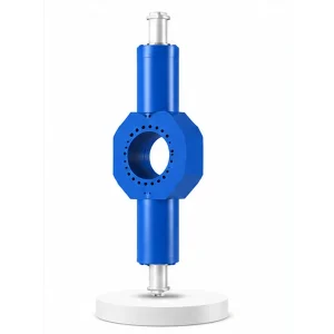
A magnetostrictive or inductive displacement transducer is integrated into the cylinder body, reporting the exact rod position to the furnace control system. The control system verifies that the lock pin is fully engaged (rod fully extended into the tilt mechanism) before allowing the electric arc to be struck. If the sensor reports anything other than "fully locked," the furnace cannot start — a hardwired safety interlock.
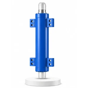
A cooling water passage is welded or brazed to the cylinder exterior. Plant cooling water circulates through this tube, keeping the cylinder body below the seal temperature rating even when the ambient temperature beside the furnace exceeds 100 °C. Water cooling on a 40 mm bore cylinder is unusual — it reflects the severity of the EAF thermal environment and the non-negotiable need for seal reliability in the lock function.
Both the extend (lock engage) and retract (lock disengage) ends of the stroke are cushioned — decelerating the rod to prevent impact on the lock pin and the tilt mechanism. Even at 17 KN thrust, repeated impact loading at the end of stroke would fatigue the lock pin bore over thousands of cycles. The cushion eliminates this impact.
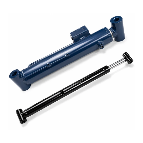
Lock Cylinder vs Tipping Cylinder — Opposite Functions, Same Furnace
The electric furnace has two cylinders with completely opposite functions on the tilt mechanism. The tipping cylinder makes the furnace tilt — driving the controlled pour of molten steel into the ladle. The lock cylinder prevents the furnace from tilting — holding the tilt mechanism stationary during melting. They are antagonists: one pushes, the other blocks.
The operational sequence is strictly interlocked: the lock cylinder must fully disengage (rod retracted, lock pin withdrawn from the tilt mechanism) before the tipping cylinder is allowed to pressurize. Conversely, the tipping cylinder must be fully depressurised and the furnace confirmed upright before the lock cylinder can re-engage. These interlocks are hardwired into the furnace control system — not software-only — so that a control system malfunction cannot command both cylinders simultaneously.
The lock cylinder's 17 KN of thrust is not intended to resist the tipping cylinder's force (which is far larger). The lock's role is to engage a mechanical pin into a locking bore — the pin, once seated, carries the structural load. The cylinder only provides the motion to insert and withdraw the pin. If the pin is engaged and the tipping cylinder accidentally pressurises (interlock failure), the pin shears before the furnace tilts — which is a mechanical failure (requiring pin replacement) but not a molten metal spill (the shearing energy absorbs the tipping force).
Fail-Safe — What Happens When Hydraulic Pressure Is Lost
A safety-critical lock must be fail-safe: if hydraulic pressure is lost (pump failure, hose burst, power outage), the lock must remain engaged — not release. The electric furnace lock cylinder achieves this through its operating logic:
The lock cylinder can be configured with a mechanical spring that drives the rod to the locked (extended) position when hydraulic pressure is removed. Unlocking requires active hydraulic pressure to retract the rod against the spring. If pressure is lost at any time, the spring re-engages the lock automatically — no operator intervention needed, no control system required.
A check valve on the retract (unlock) port ensures that the cylinder cannot retract unless pilot pressure from the control system deliberately opens the check valve. Hose burst on the retract line does not cause the cylinder to retract — the check valve holds the lock in position. Unlocking requires a deliberate, two-stage command: pilot pressure opens the check valve, then system pressure retracts the rod.
The built-in sensor continuously reports the rod position to the furnace control system. If the rod drifts even 1 mm from the fully-locked position during melting (indicating a slow leak or mechanical creep), the control system triggers an alarm and initiates an emergency power-down sequence — shutting off the electric arc and notifying the operator before the lock disengages enough to allow furnace tilt.
Manufacturing — Small Bore, Maximum Reliability
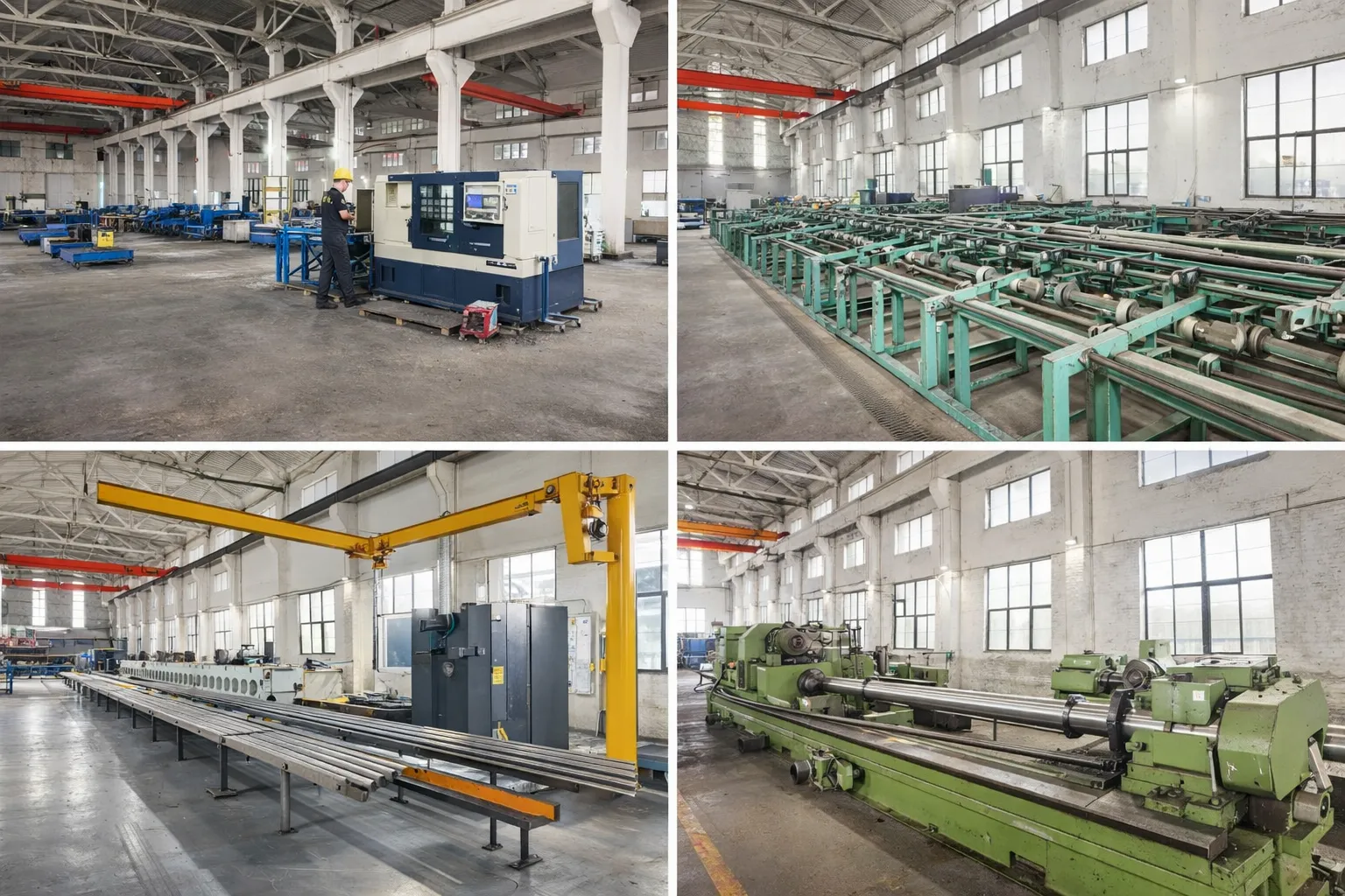
At 40 mm bore, the lock cylinder is physically small — but the machining precision and quality control are the same as the 580 mm cover lifting cylinder (#14) that shares the same furnace. The bore is honed to Ra 0.2–0.4 µm, the rod is chrome plated and ground, the V-group seal packing is assembled with verified compression, and the displacement sensor is calibrated against a traceable reference.
The water cooling tube is pressure-tested separately from the hydraulic bore — verifying no cross-leakage between the cooling water circuit and the hydraulic oil circuit. Cross-contamination (water entering the hydraulic system) would be a severe reliability risk — water in hydraulic oil causes cavitation, corrosion, and seal degradation across the entire furnace hydraulic circuit, not just the lock cylinder.
Every lock cylinder is hydrostatic tested at 1.5× working pressure (21 MPa), functionally tested for full-stroke extension and retraction with cushion verification, and the displacement sensor output is verified at the locked and unlocked positions. The test certificate for a lock cylinder is more detailed than for most larger cylinders — reflecting its safety-critical classification.
OEM & ODM
FAQ
Related Categories
Další informace
| Editor |
|---|
Související produkty
-
Injection Molding Machine Reciprocating Cylinder (Mold Shifting Cylinder)
-
Hydraulic Press Lateral Shift Anvil Cylinder
-
Hydraulic Press Cushion Cylinder
-
Hydraulic Press Centering Cylinder
-
Hydraulic Press Rear Side Shift Cylinder
-
Cement Equipment Roll over Cylinder
-
Electric Furnace Cover Rotating Cylinder
-
Hydraulic Press Return Cylinder


