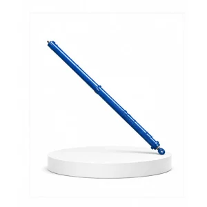
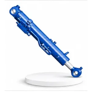
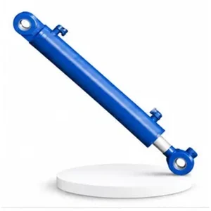
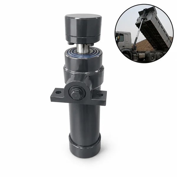
Mobile Crane Outrigger Expansion Cylinder

Two Cylinders, Two Directions — The Outrigger Pair
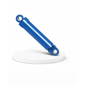
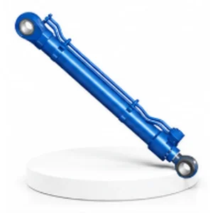
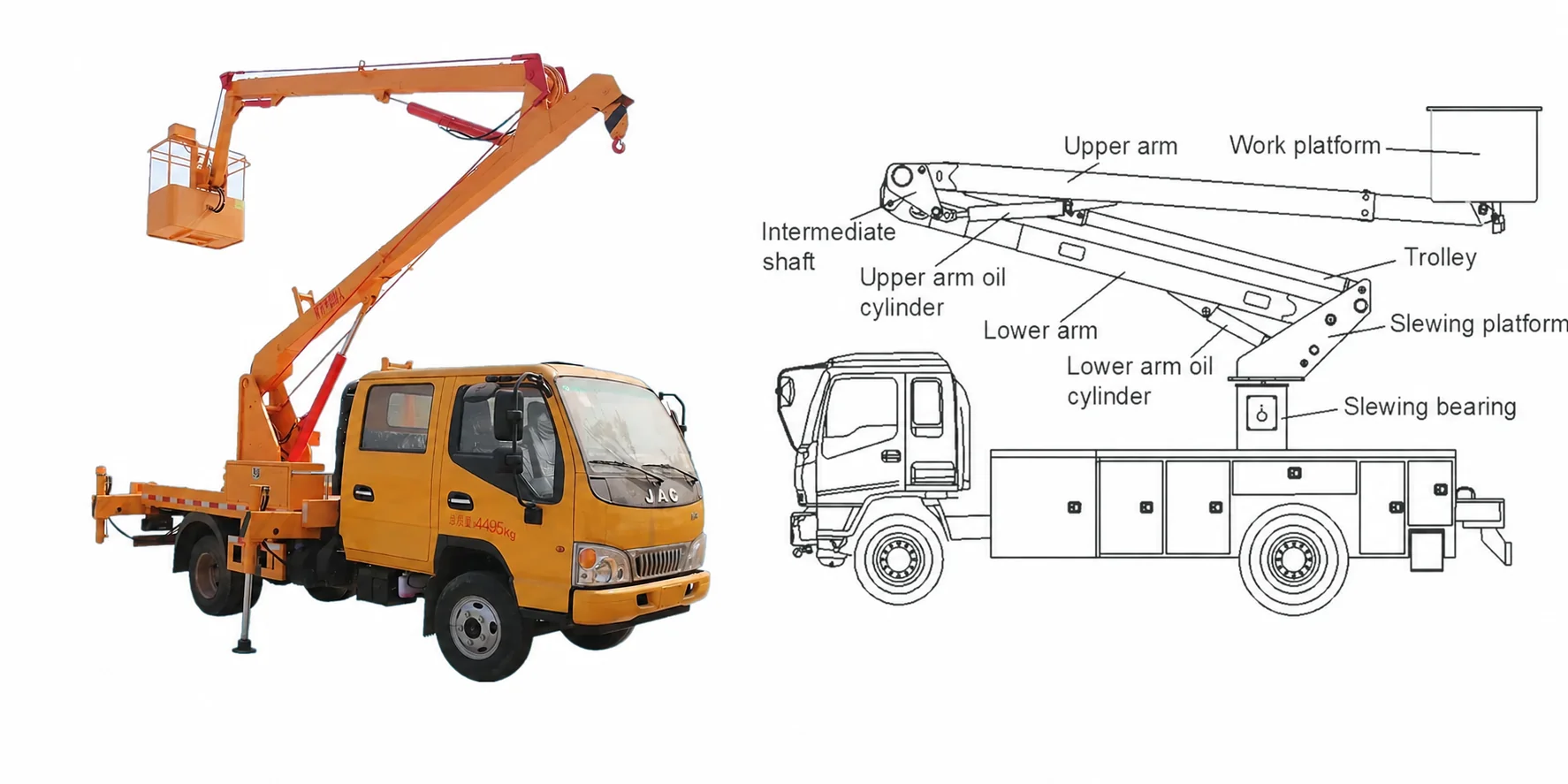
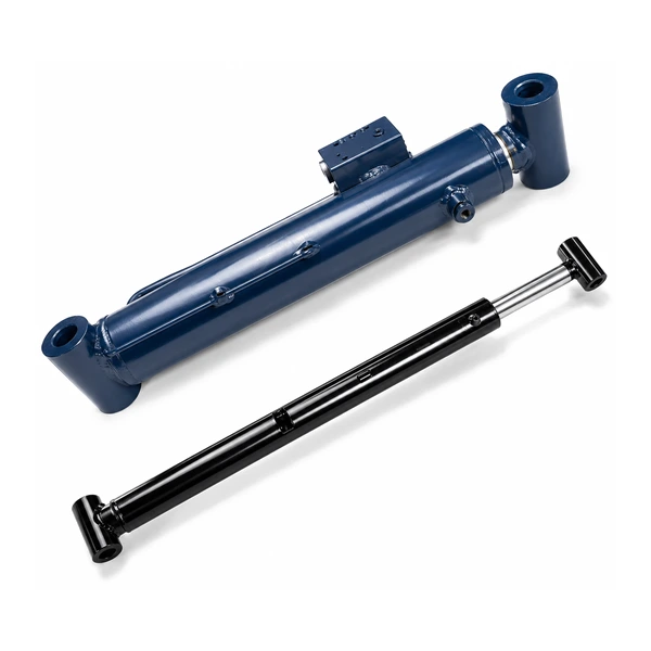
Each outrigger assembly on a mobile crane uses two cylinders working in sequence. The expansion cylinder (#21) moves first — sliding the outrigger beam horizontally outward from the chassis to maximise the distance between opposite pads. Then the outrigger cylinder (#19) moves second — extending vertically downward from the end of the beam to press the pad into the ground.
The expansion cylinder has the smallest bore in the crane cylinder family (50–75 mm) because its job is motion, not force. It only needs to overcome the friction of the beam sliding in its guide channel — the beam slides horizontally on wear pads, and the resistance is modest (a few kilonewtons). The large outrigger cylinder (#19, up to 360 mm bore) handles the heavy force — supporting the crane's weight vertically.
This separation of horizontal motion (small cylinder, long stroke) and vertical force (large cylinder, short stroke) is the standard architecture for mobile crane outrigger systems. Korea Ever-Power manufactures both cylinders as a matched pair within the mobile machinery hydraulic cylinder range.
Technical Specifications
| Parameter | Specification |
|---|---|
| Product | Mobile Crane Outrigger Expansion Cylinder |
| Function | Extend the outrigger beam horizontally |
| Bore Diameter | 50 mm – 75 mm |
| Rod Diameter | 25 mm – 55 mm |
| Stroke | ≤ 2,500 mm |
| Working Pressure | Maximum 35 MPa |
| Application | Mobile Crane (outrigger beam extension) |
| Certification | ISO 9001 · 100% hydrostatic tested |
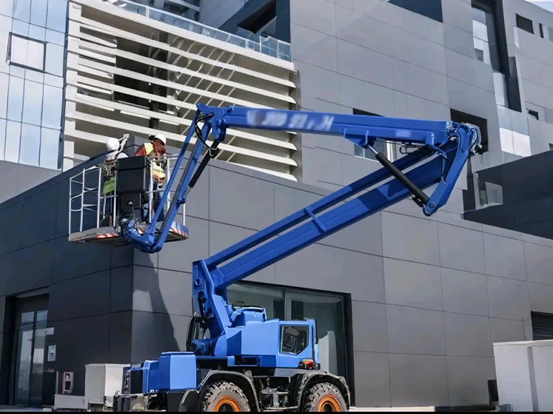
Wider = Safer — How 2.5 Metres of Horizontal Extension Increases Lifting Capacity
A crane's resistance to tipping is proportional to the distance between the outrigger pads. Doubling the outrigger span roughly doubles the stabilising moment — which means the crane can lift proportionally more load at the same radius. The expansion cylinder's 2,500 mm stroke can increase the outrigger span from the retracted (chassis-width) position to the fully extended position by up to 5 metres (2,500 mm per side × 2 sides).
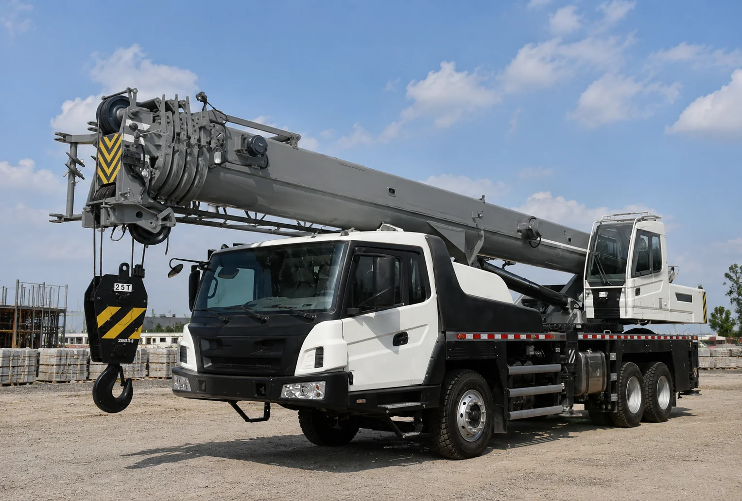
With the outrigger beams retracted (for road travel within legal width limits), the outrigger pads are positioned close to the chassis — typically 2.5–3.5 metres apart. This narrow footprint provides minimal stability and severely limits the crane's lifting capacity. Many crane load charts show zero or minimal capacity at retracted outrigger position.
With both expansion cylinders fully extended, the outrigger span reaches 7–8.5 metres — more than double the retracted width. This wide footprint maximises the stabilising moment and unlocks the crane's full rated capacity. The load chart's "fully extended outrigger" column shows the highest permitted loads — every crane operator aims for full extension on every lift.
When site constraints prevent full extension (adjacent buildings, traffic lanes, excavations), the expansion cylinder extends only partway. The load chart provides intermediate capacity columns for partial extension. The cylinder's stroke sensor reports the actual extension percentage to the crane's moment limiter, which automatically selects the correct capacity column. Contact the Korea Ever-Power engineering team for outrigger expansion specifications.
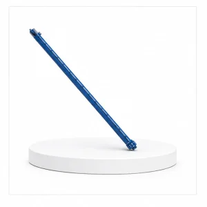
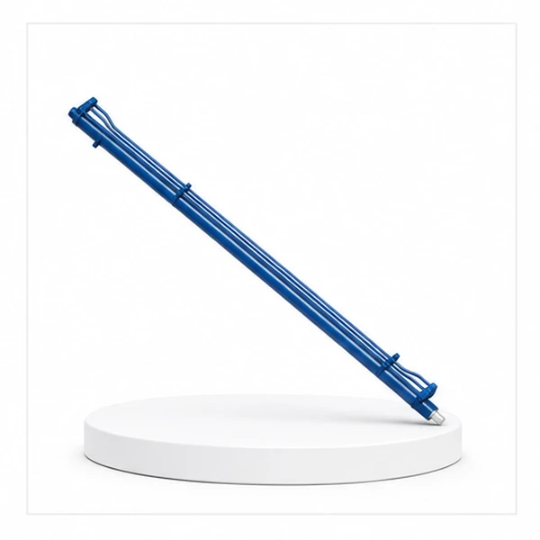
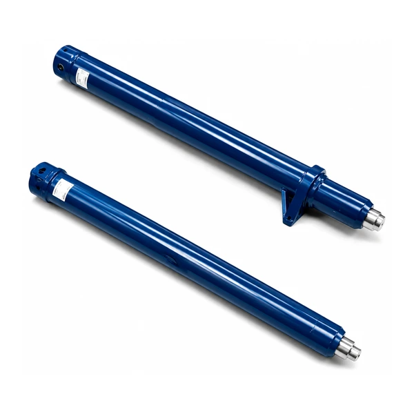
2,500 mm Stroke from a 50–75 mm Bore — Engineering a Slender Cylinder
The expansion cylinder has an extreme length-to-diameter ratio — 2,500 mm stroke from a 50–75 mm bore produces a retracted cylinder length of approximately 3,000 mm with an outer diameter of only 80–100 mm. This slender proportions creates two engineering challenges that Korea Ever-Power addresses in the cylinder design:
When retracting the outrigger beam (pulling it back toward the chassis), the rod is in tension — no buckling risk. But during extension, the rod is in compression as it pushes the beam outward. At 2,500 mm extension with a 25–55 mm rod, buckling analysis is mandatory. Korea Ever-Power verifies the rod's Euler buckling capacity at full extension, with the safety factor required by the crane's structural design code.
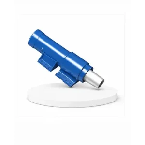
The outrigger beam can weigh 200–500 kg. When the expansion cylinder is fully extended, the beam's weight applies a bending moment at the rod guide (the bearing at the cylinder's head where the rod exits). An undersized guide allows the rod to cock sideways — creating uneven seal wear and premature leakage. Korea Ever-Power specifies an oversized guide bearing length (≥1.5× bore diameter) to distribute the side load across a larger bearing surface.
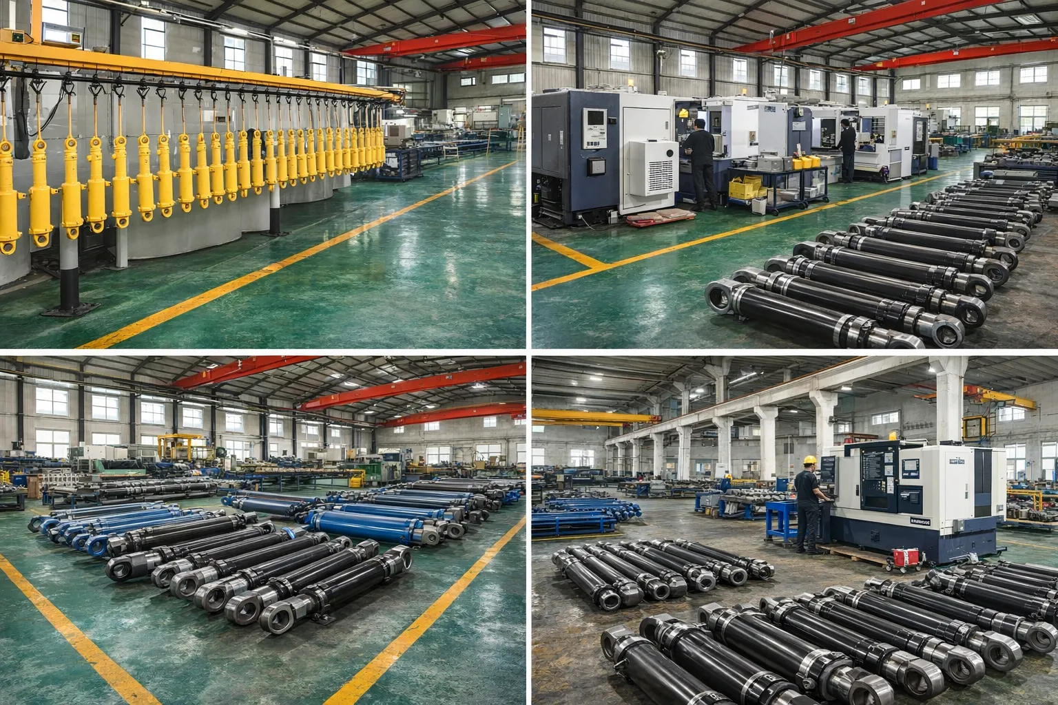
Manufacturing Process
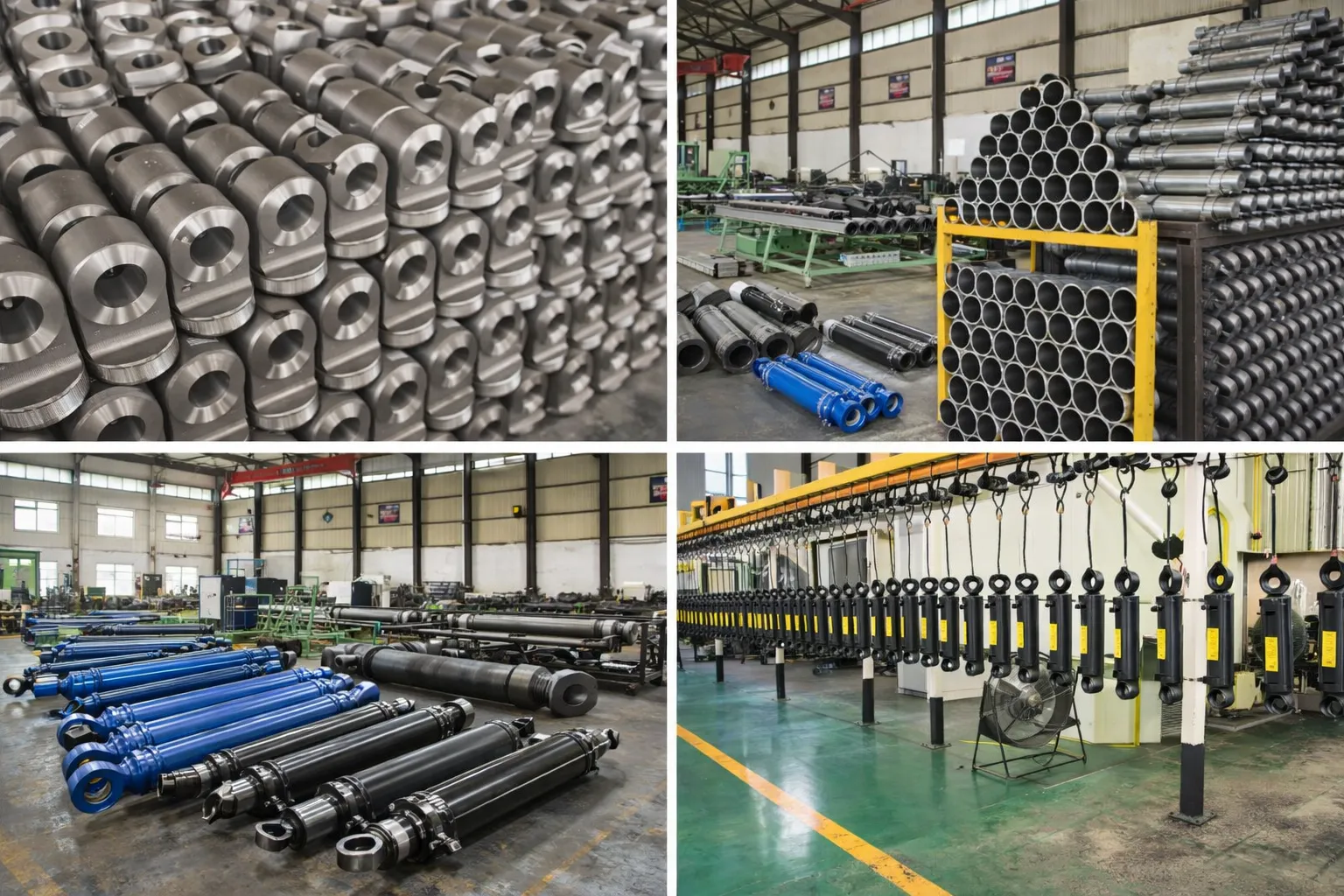
The small bore (50–75 mm) is honed to Ra 0.2–0.4 µm. Rod straightness is verified to ≤0.1 mm/metre over the full 2,500 mm length — critical for preventing seal damage during retraction of a long, slender rod. Chrome plating is 50–80 µm (outdoor service with exposure to road splash and construction site debris).
Seals are polyurethane piston seal + NBR rod seal + double-lip wiper, rated for -30 °C to +80 °C. The position-locking function (holding the beam at a set extension) uses a pilot-operated check valve on the extend port — preventing the beam from creeping inward under vibration or incidental contact during crane operation.
Every expansion cylinder is hydrostatic tested at 1.5× rated pressure (52.5 MPa) and stroke-tested for smooth full extension and retraction without stick-slip — verifying that the long, slender rod travels straight and the seals function correctly over the entire 2,500 mm travel range.
OEM & ODM
FAQ
Related Categories
Additional information
| Editor |
|---|