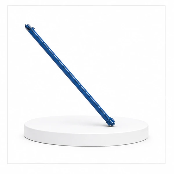
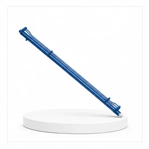
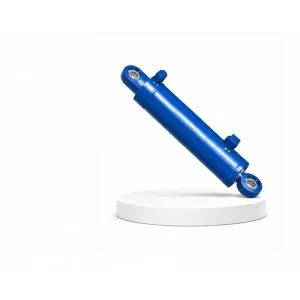
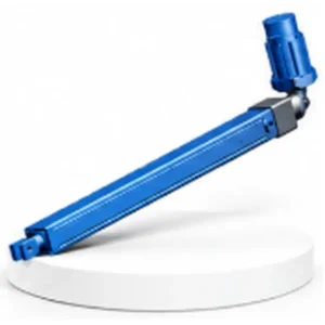
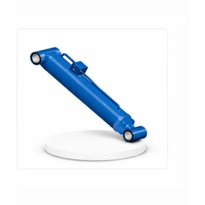
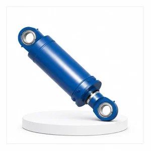
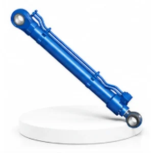
Mobile Crane Luffing Cylinder

What the Luffing Cylinder Does — And Why It Defines the Crane
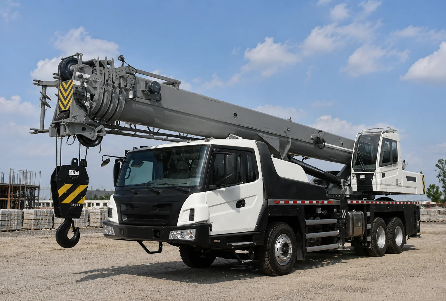
On a mobile crane, "luffing" is the motion of raising or lowering the boom — changing the angle between the boom and the horizontal plane. A boom angled steeply upward (70–80°) places the hook almost directly above the crane, giving maximum height but minimum reach. A boom angled lower (20–30°) extends the hook far from the crane, giving maximum reach but reduced height and load capacity.
The luffing cylinder is the single actuator that controls this angle. It connects the crane's superstructure to the boom base, pushing the boom upward when it extends and lowering the boom when it retracts. Every entry on the crane's load chart — the table that tells the operator the maximum safe load at each radius — is determined by the luffing cylinder's ability to hold the boom at the required angle under the rated load.
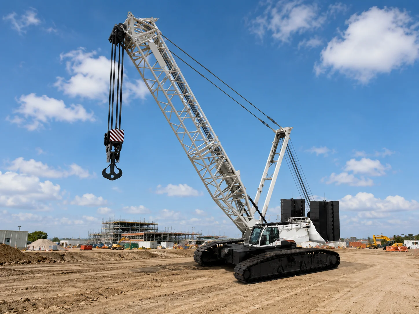
Korea Ever-Power manufactures luffing cylinders as the flagship product of the mobile machinery hydraulic cylinder range — covering boom luffing for truck cranes, all-terrain cranes, rough-terrain cranes, and crawler cranes from 25-tonne to 1,200-tonne lifting capacity.
Technical Specifications
| Parameter | Specification |
|---|---|
| Product | Mobile Crane Luffing Cylinder |
| Function | Up-and-down pitching rotation of the boom — main driving force for lifting |
| Bore Diameter | 100 mm – 560 mm |
| Rod Diameter | 50 mm – 480 mm |
| Stroke | ≤ 5,000 mm |
| Working Pressure | Maximum 36 MPa |
| Application | Mobile Crane (truck crane, all-terrain, rough-terrain, crawler) |
| Certification | ISO 9001 · 100% hydrostatic tested · load-holding verified |
Why the Luffing Cylinder Is the Most Safety-Critical Component on the Crane
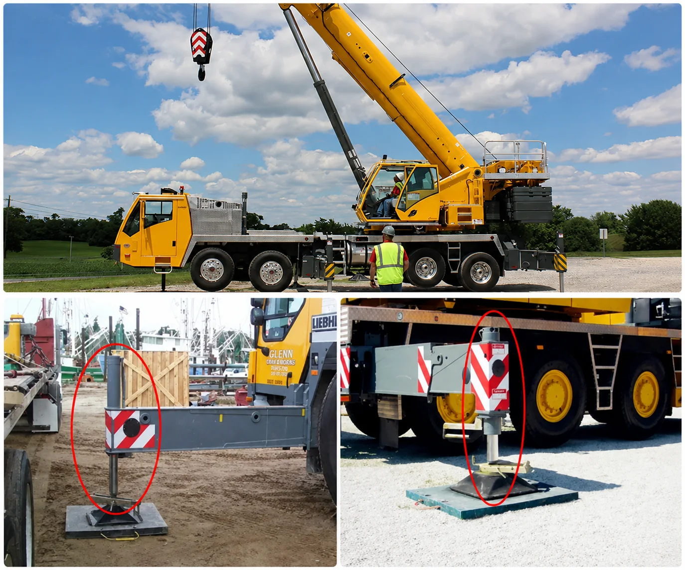
Every other crane cylinder has a mechanical backup or a fail-safe condition. The outrigger cylinders (#19) rest on the ground — if hydraulic pressure fails, the outrigger stays down. The telescopic cylinder (#18) is enclosed inside the boom — if it leaks, the boom stays at its current length. But the luffing cylinder holds the boom against gravity. If it loses pressure, the boom drops.
Every luffing cylinder includes a pilot-operated counterbalance valve (also called a holding valve or load-holding valve) mounted directly on the cylinder port — not on a remote valve block connected by hoses. This valve mechanically locks the oil in the cylinder. Even if the supply hose ruptures, the counterbalance valve holds the boom in position. The boom cannot drop unless the operator deliberately commands it.
The luffing cylinder barrel sees millions of pressure cycles over its service life — each lift cycle applies and releases the full working pressure. The barrel wall thickness, weld quality, and material grade are specified for fatigue life exceeding the crane's design life (typically 20–25 years or 10,000+ operating hours). Korea Ever-Power uses seamless precision-honed steel tube with full-penetration circumferential welds, ultrasonically inspected.
At 5,000 mm stroke with a 480 mm rod, the extended rod acts as a compression column under the full boom load. Euler buckling analysis is mandatory — the rod diameter, material strength, and mounting geometry must ensure a buckling safety factor of ≥3 at the worst-case boom angle. Korea Ever-Power performs FEA (finite element analysis) for every luffing cylinder design to verify rod stability under combined axial and lateral loading.
Boom Angle and the Load Chart — The Geometry That Governs Everything
A crane's load chart shows the maximum load at each working radius (the horizontal distance from the crane's centre of rotation to the hook). The working radius depends directly on the boom angle: a longer boom at a lower angle = greater radius = lower permitted load. The luffing cylinder sets the boom angle, so the luffing cylinder indirectly controls the crane's load capacity at every lift.
The force the luffing cylinder must produce changes dramatically with boom angle. When the boom is nearly vertical (75–85°), gravity acts almost in line with the boom — the luffing cylinder carries relatively little load. As the boom lowers toward horizontal, the gravitational moment arm increases — and the cylinder force required to hold the boom increases sharply. At a typical working angle of 30°, the cylinder force can be 3–5 times higher than at 75°.
This is why the mobile crane luffing cylinder has the largest bore in the mobile machinery hydraulic cylinder family — up to 560 mm — combined with the highest working pressure (36 MPa). The bore area × pressure must produce enough force to hold the boom plus the rated load at the lowest working angle in the crane's load chart.
Seven Cylinders, One Crane — The Complete Mobile Crane Hydraulic System
The luffing cylinder is the first of seven hydraulic cylinder types that Korea Ever-Power manufactures for mobile cranes. Each cylinder serves a different function on the crane:
| Cylinder | Bore | Stroke | MPa | Function |
|---|---|---|---|---|
| Luffing | 100–560 | ≤5,000 | 36 | Boom angle control |
| Telescopic | 75–360 | ≤22,000 | 42 | Boom extension |
| Outrigger | 70–360 | ≤800 | 42 | Stabilizer legs |
| Suspension | 85–180 | ≤300 | 35 | Chassis damping |
| Outrigger Expansion | 50–75 | ≤2,500 | 35 | Horizontal beam extension |
| Counterweight | 85–320 | ≤1,500 | 35 | Counterweight positioning |
| Steering | 63–200 | ≤1,000 | 35 | Chassis steering |
Korea Ever-Power supplies all seven cylinder types for crane OEMs — engineered for the same crane's hydraulic system, pressure rating, and service environment. Single-source supply ensures system compatibility across the entire machine.
Additional information
| Editor |
|---|
Related products
-
Mobile Crane Outrigger Expansion Cylinder
-
Mobile Crane Steering Cylinder
-
Aerial Work Platform Electric Cylinder
-

Aerial Work Platform Telescopic Cylinder
-
Aerial Work Platform Outrigger Cylinder
-
Aerial Work Platform Rotary Actuator
-
Mobile Crane Suspension Cylinder
-
Large Excavator Stick Cylinder (Arm Cylinder)


