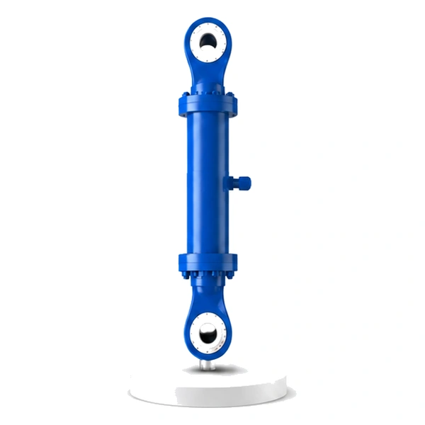
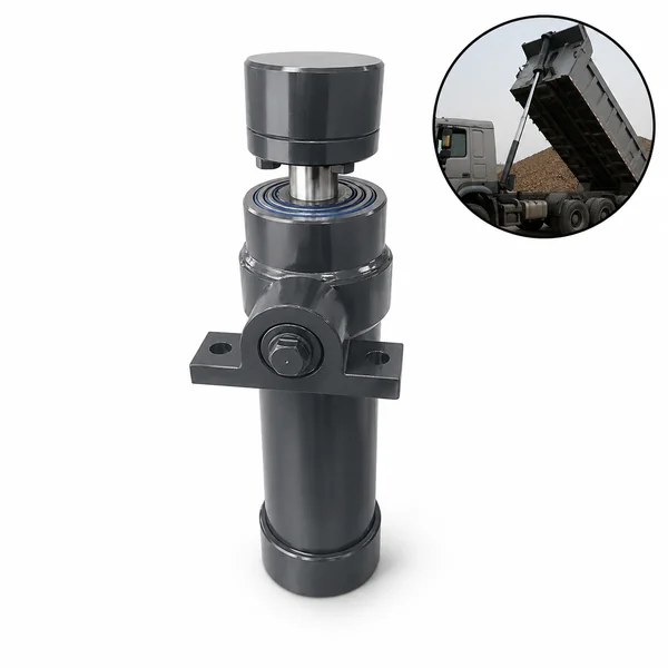
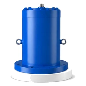
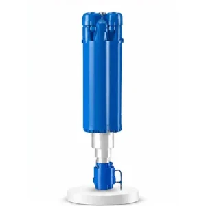
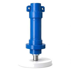
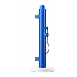
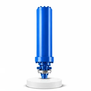
Cement Equipment Vertical Mill Cylinder

Vertical Mill Cylinder
Same Spec Sheet.
Different Machine.
Different Engineering.
Bore 200–700 mm. Thrust up to 5,387 KN. Stroke ≤500 mm. Pressure 14 MPa. These numbers are identical to the roller press cylinder (#20). But this cylinder operates on a vertical roller mill — where the force direction, the grinding geometry, the lever mechanism, and the dual push/lift requirement are all fundamentally different.
How a Vertical Roller Mill Grinds — A Different Geometry Entirely
A vertical roller mill (VRM) consists of a horizontal rotating table with 2–4 grinding rollers pressed onto it from above. Raw material is fed onto the centre of the table. As the table rotates, centrifugal force throws the material outward — under the grinding rollers. Each roller, pressed downward by its hydraulic cylinder, crushes the material against the table surface. A dam ring around the table edge retains the material until it is ground fine enough for the hot gas stream to carry it upward to the classifier above the rollers.
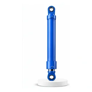
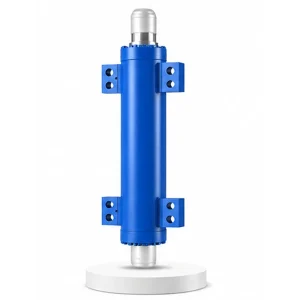
The vertical mill cylinder pushes each roller downward onto the material bed — but not directly. The roller is mounted on a rocker arm (a lever that pivots on the mill housing). The cylinder pushes one end of the rocker arm; the roller is at the other end. This lever mechanism multiplies the cylinder's force and converts horizontal cylinder thrust into the vertical grinding force on the roller. Korea Ever-Power manufactures vertical mill cylinders as part of the industrial engineering hydraulic cylinder programme.
Technical Specifications
| Parameter | Value |
|---|---|
| Product | Cement Equipment Vertical Mill Cylinder |
| Function | Press grinding rollers onto the table / Lift rollers for maintenance |
| Bore Diameter | 200 mm – 700 mm |
| Rod Diameter | 130 mm – 500 mm |
| Stroke | ≤ 500 mm |
| Maximum Thrust | 5,387 KN (bore 700 mm / pressure 14 MPa) |
| Working Pressure | Up to 14 MPa |
| Certification | ISO 9001 · 100% hydrostatic tested |
Same Cylinder Specs — Different Machine, Different Duty
The vertical mill cylinder and the roller press cylinder (#20) share identical bore, rod, stroke, and thrust ranges. But the machines they serve are fundamentally different — and the engineering challenges differ accordingly.
| Feature | Roller Press (#20) | Vertical Mill (#21) |
|---|---|---|
| Force direction | Horizontal →← | Vertical ↓ (via rocker arm) |
| Grinding geometry | 2 rollers squeeze material | Rollers press onto table |
| Cylinders per machine | 2 (one per side) | 2–4 (one per roller) |
| Roller lifting required? | No (just retract) | Yes — must lift rollers off table |
| Lever mechanism | Direct push | Rocker arm (force multiplication) |
| Material on table moves by | Roller rotation (driven) | Table rotation + centrifugal force |
The Rocker Arm — How a Horizontal Cylinder Produces Vertical Grinding Force

The vertical mill cylinder is typically mounted horizontally or at a shallow angle on the mill housing — not vertically above the roller. The force conversion from horizontal to vertical happens through a rocker arm: a heavy steel lever that pivots on a bearing mounted on the mill body.
The cylinder rod connects to one end of the rocker arm. The grinding roller shaft connects to the other end. The pivot is between them. When the cylinder extends, it pushes the rocker arm upward at the cylinder end — which pushes the roller end downward onto the grinding table. The lever ratio (distance from pivot to cylinder attachment ÷ distance from pivot to roller shaft) determines the force multiplication: a 2:1 ratio means the cylinder's 5,387 KN produces 10,774 KN of vertical grinding force on the roller.
This rocker arm mechanism is unique to the vertical mill — the roller press cylinder (#20) pushes the movable roller directly, without any lever mechanism. The rocker arm adds complexity (an additional pivot bearing, a structural lever arm) but provides force multiplication that allows a smaller cylinder to produce the same grinding force — or the same cylinder to produce significantly more grinding force than the roller press at the same pressure.
Dual Function — Push Down to Grind, Pull Up to Lift
The roller press cylinder only needs to push — retraction simply relieves the grinding force, and the rollers stay in contact with the material by gravity. The vertical mill cylinder must do both: push the rollers down for grinding AND pull the rollers up off the table — a retraction function that the roller press never needs.
This dual push/pull requirement means the vertical mill cylinder must generate meaningful force in both directions — the retraction force (rod-side annular area × pressure) must be enough to lift the roller, the rocker arm, and overcome the roller's weight component on the rocker geometry. Korea Ever-Power verifies both extend and retract forces during the engineering phase. Contact the hydraulic cylinder engineering team for vertical mill cylinder specifications.
Material Bed Dynamics — Why the Vertical Mill Cylinder Sees Different Loads
On a roller press (#20), the material enters the nip between two rollers from above, in a controlled stream. On a vertical mill, the material is spread across a rotating table by centrifugal force — creating a material bed that is thicker near the centre (where the feed drops) and thinner near the dam ring at the outer edge (where the ground material overflows). The rollers grind the material as the table sweeps it beneath them.
This non-uniform bed creates load variations that the vertical mill cylinder must absorb. As the table rotates, each roller encounters alternating thick and thin zones — the cylinder must compress and extend rhythmically as the material bed thickness varies under the roller. This oscillating load is typically at the table rotation frequency (10–30 RPM) — slower than the roller press vibration but larger in amplitude (10–30 mm of roller travel per revolution).
The nitrogen accumulator absorbs these oscillations — compressing as the thick zone passes under the roller (roller lifts, cylinder retracts slightly) and expanding as the thin zone passes (roller drops, cylinder extends slightly). Without the accumulator, the pressure spikes on the thick zone would overstress the cylinder and the rocker arm bearings.
Three VRM Applications in Cement Production
The dominant VRM application in cement. Grinds limestone, clay, and additives into raw meal for the kiln. The VRM handles drying and grinding simultaneously — hot kiln exhaust gas passes through the mill, drying the raw material while it is ground. The cylinder must tolerate the thermal cycling from the hot gas (80–350 °C) passing through the mill body.
VRMs grind the solid fuel used to fire the kiln. Coal and petcoke grinding operate in an inert atmosphere (nitrogen or CO₂) to prevent explosion — the cylinder and its hydraulic connections must be sealed against gas leakage into or out of the mill housing. The cylinder must also tolerate the explosion-proof environment classification of the grinding area.
The newest VRM application — replacing ball mills for final cement grinding. This demands the finest particle size control and the most consistent grinding force. The vertical mill cylinder's force consistency directly determines the cement fineness — and therefore the compressive strength of the concrete made from that cement.
Manufacturing
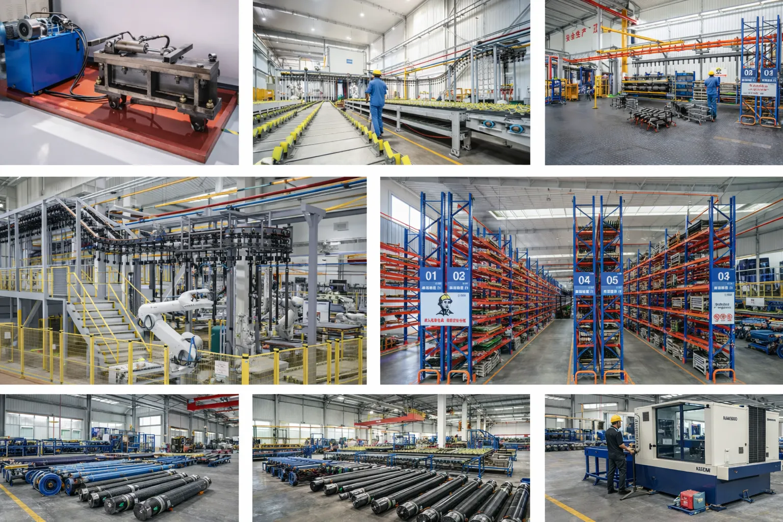
The vertical mill cylinder shares the same bore and rod range as the roller press cylinder — and the same manufacturing equipment produces both. The critical difference is in the dual-direction force verification: both the extend (grinding push) and retract (roller lift) forces are calculated, verified against the rocker arm geometry, and tested during factory functional testing. The retract force must be sufficient to lift the roller, the rocker arm, and the roller shaft assembly — which can total 20–50 tonnes depending on the mill size. Korea Ever-Power verifies the retract force by calculating the rod-side annular area (bore area minus rod area) × pressure, confirming it exceeds the total lift load with a safety margin. Every vertical mill cylinder is hydrostatic tested at 1.5× working pressure on both ports and functionally tested for full extend and retract at the specified speeds.
OEM & ODM
FAQ
Related Categories
Informazioni aggiuntive
| Editor |
|---|
Prodotti correlati
-
Injection Molding Machine Reciprocating Cylinder (Mold Shifting Cylinder)
-
Cement Equipment Roller Press Cylinder
-
Hydraulic Press Clamping Cylinder
-
Electric Furnace Tipping Cylinder
-
Hydraulic Press Centering Cylinder
-
Injection Molding Machine Ejection Cylinder
-
Electric Furnace Lifting Cylinder
-
Hydraulic Press Master Cylinder


