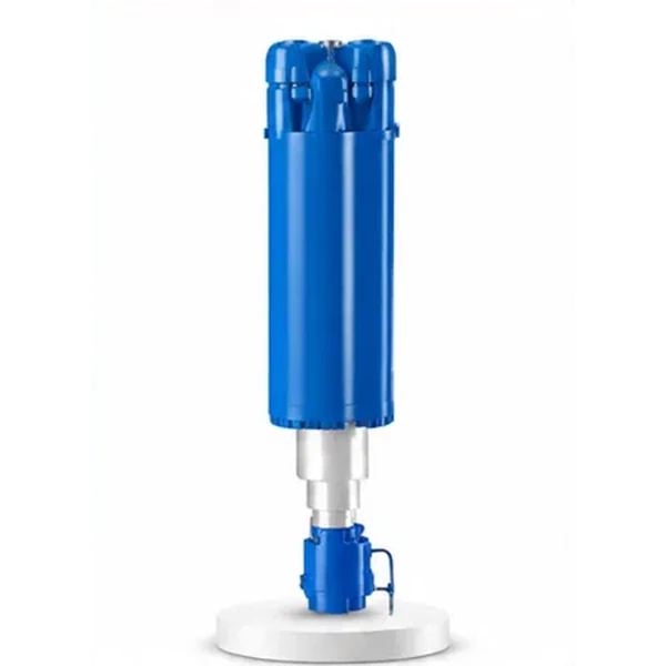
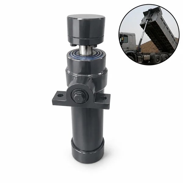
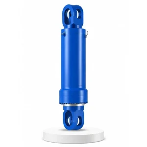
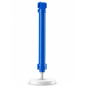
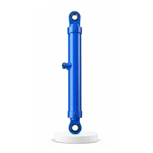
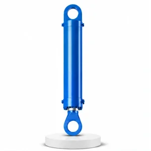
Hydraulic Press Clamping Cylinder

Maximum Force.
Minimum Stroke.
Never Let Go.
Every other press cylinder acts and returns. The clamping cylinder acts and holds — maintaining full grip pressure on a 1,200 °C steel billet for the entire forging sequence, through every press stroke, every manipulator rotation, every lateral shift. If the grip fails, the billet falls. There is no second chance.
Grip — Not Move
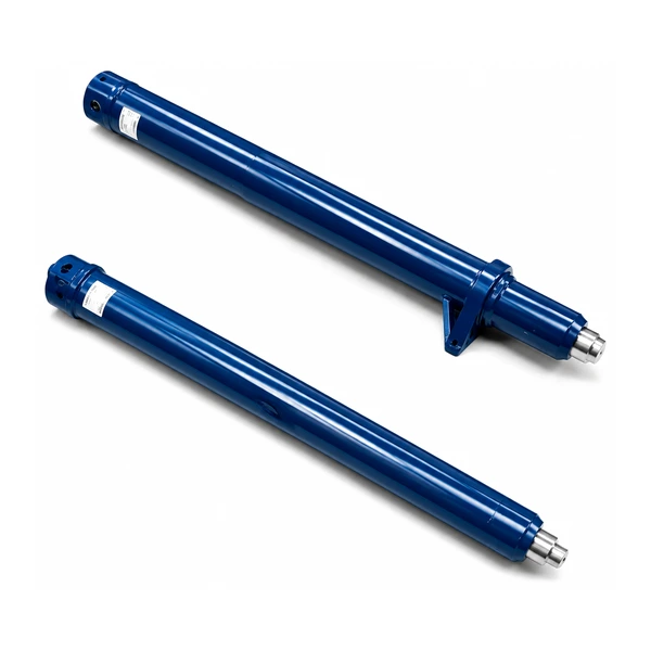
The master cylinder presses down and returns. The return cylinder lifts up and retracts. The lateral shift cylinder slides sideways and slides back. Every other cylinder in the press system performs a motion — extend, do work, retract. The clamping cylinder is fundamentally different: it closes the jaws, then stays at pressure. Its job is not motion. Its job is continuous grip.
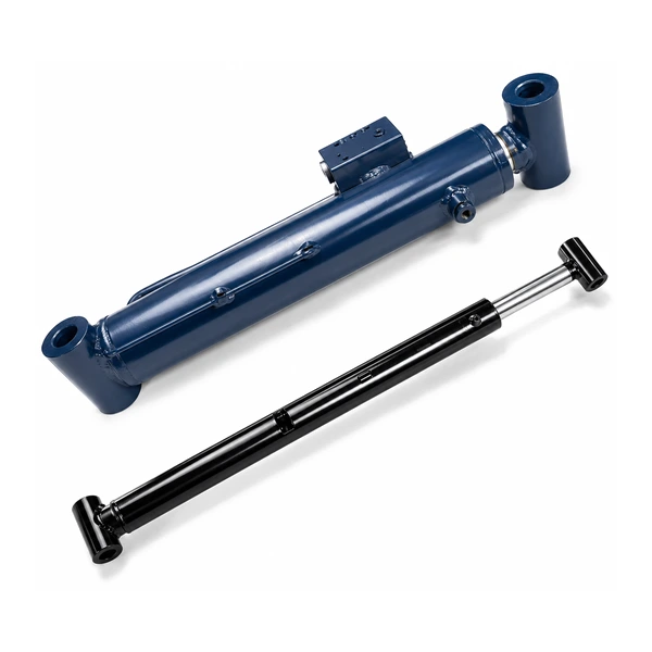
The manipulator clamp head grips the billet between two jaws. The clamping cylinder drives these jaws together, squeezing the billet with enough force that the billet cannot slip — not during the press stroke (which sends shock waves through the billet), not during manipulator rotation (which applies torque), and not during lateral shifting (which applies lateral acceleration). The cylinder must hold this grip for the entire forging sequence — which can last 5–30 minutes per billet, encompassing dozens of press strokes. Korea Ever-Power engineers clamping cylinders for this continuous-duty requirement as part of the industrial engineering hydraulic cylinder programme.
Technical Specifications
| Parameter | Value |
|---|---|
| Product | Hydraulic Press Clamping Cylinder |
| Function | Grip the steel ingot or billet in the manipulator clamp head |
| Bore Diameter | 125 mm – 700 mm |
| Rod Diameter | 80 mm – 520 mm |
| Stroke | ≤ 1,200 mm |
| Maximum Thrust | 9,621 KN (bore 700 mm / pressure 25 MPa) |
| Working Pressure | Up to 25 MPa |
| Certification | ISO 9001 · 100% hydrostatic tested |
Engineering Insight — The Physics of Not Dropping a 10-Tonne Billet
The clamping force is not arbitrary — it is calculated from the billet weight, the friction between the jaw faces and the billet surface, and a safety factor that accounts for the dynamic forces during forging (shock, vibration, inertia from manipulator movement).
Required grip force:
Fclamp = (W × S) ÷ (µ × n)
W = billet weight (N) · S = safety factor (typically 3–5) · µ = friction coefficient (0.15–0.3 for steel-on-steel at temperature) · n = number of gripping faces (typically 2)
The safety factor of 3–5 accounts for the press shock force (transmitted through the billet into the jaws), the inertial force during rapid manipulator rotation, and the possibility of reduced friction from oxide scale on the billet surface. Korea Ever-Power sizes the clamping cylinder bore to deliver the calculated grip force at the operating pressure — with the full safety margin. Contact the hydraulic cylinder engineering team for clamping force calculations.
Continuous Pressure Hold — A Different Duty Cycle
Most hydraulic cylinders cycle: extend → work → retract → repeat. The clamping cylinder extends to close the jaws, then holds at full pressure for 5–30 minutes while the forging sequence proceeds. During this hold period, the cylinder must maintain pressure without any drop — because any pressure loss relaxes the jaw grip on the billet.
This continuous hold creates different engineering demands than cyclic operation. The seals must resist static friction (stiction) — the tendency of elastomer seals to bond to the bore surface under sustained pressure. When the jaws finally open after a long hold, the seals must break free cleanly without stick-slip. Korea Ever-Power uses low-stiction seal compounds (PTFE-bronze composite piston seals) for clamping cylinders to ensure smooth jaw opening after prolonged pressure holds.
The hydraulic circuit includes a pressure-maintaining valve (accumulator or check valve) that keeps the cylinder pressurised even if the pump is serving other cylinders on the manipulator. This guarantees uninterrupted grip regardless of what else the hydraulic system is doing — the tilt cylinder, the traverse cylinder, and the rotation cylinder can all be active without affecting the clamping pressure.
125 mm to 700 mm Bore — Why the Range Is So Wide
No other auxiliary press cylinder spans such a wide bore range. The reason is that clamping forces vary enormously depending on what is being gripped — from a 500 kg billet on a small ring-rolling manipulator to a 50-tonne ingot on a heavy free-forging manipulator. The bore diameter scales directly with the required clamping force.
Ring rolling and pipe forging manipulators. Billets 0.5–5 tonnes. Clamping forces 300–1,200 KN. Fast jaw opening for rapid billet changeover during high-volume ring production. Compact cylinder fits within the manipulator arm envelope.
General-purpose forging manipulators. Billets 5–20 tonnes. Clamping forces 1,500–4,000 KN. The most common size range — covers the majority of open-die forging operations producing shafts, blocks, and stepped forgings.
Heavy free-forging manipulators on 40–80 MN presses. Billets 20–50+ tonnes. Clamping forces 5,000–9,621 KN. These are among the largest auxiliary cylinders manufactured — the 700 mm bore approaches the size of a small master cylinder. The grip force must hold multi-tonne ingots during the shock of an 80 MN press stroke.
When the Grip Fails — Consequences and Prevention

A clamping cylinder failure during forging has immediate, severe consequences. The hot billet — weighing tonnes, at temperatures that instantly ignite anything it touches — drops from the manipulator onto the press bolster, the floor, or worse. The billet is unpredictable: it may bounce, roll, or shatter if it has internal cracks from the forging process.
Prevention relies on three layers. First, the clamping force calculation includes a safety factor of 3–5×, so the actual grip far exceeds the minimum needed. Second, the hydraulic circuit includes a pilot-operated check valve on the clamp port that locks the cylinder at pressure even if the supply line loses pressure. Third, pressure sensors monitor the clamp circuit continuously — any pressure drop triggers an immediate press-stop interlock and an alarm.
Korea Ever-Power designs every clamping cylinder with the check-valve mounting face integrated into the cylinder head — not as a remote installation. This eliminates the hose segment between the cylinder and the check valve, removing the most common failure point (hose burst between cylinder and valve = instant pressure loss = instant grip loss).
Manufacturing
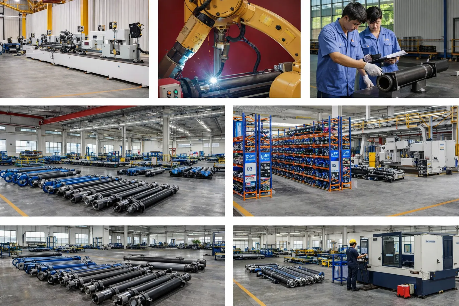
The clamping cylinder's short stroke (≤1,200 mm) means the barrel is compact, but the large bore (up to 700 mm) demands heavy-duty machining: CNC boring and honing at 700 mm diameter requires large-swing lathes and custom honing tooling. The piston — up to 700 mm diameter — is a substantial forged component that must be machined, sealed, and assembled with tight concentricity to the bore. Korea Ever-Power's large-bore machining capability covers the full 125–700 mm range. Seals for the continuous-hold duty cycle are selected from low-stiction compounds (PTFE-bronze composite) to prevent jaw sticking after prolonged pressure holds. Every cylinder is hydrostatic tested at 1.5× working pressure with a hold test — verifying zero pressure drop over a defined period that simulates the continuous-grip duty cycle.
OEM & ODM
FAQ
Related Categories
其他信息
| Editor |
|---|
相关产品
-
Tipping Cylinder for Vulcanizing Machine
-
Electric Furnace Cover Lifting Cylinder
-
Injection Molding Machine Shooting Cylinder
-
Hydraulic Press Rear Side Shift Cylinder
-
Electric Furnace Mast Cylinder
-
Hydraulic Press Mobile Workbench Cylinder
-
Electric Furnace Cover Rotating Cylinder
-
Hydraulic Press Leveling Cylinder


