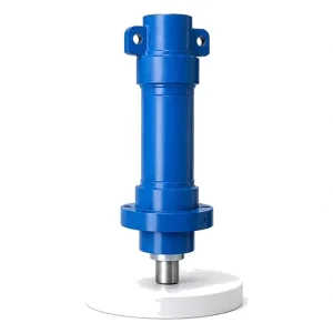
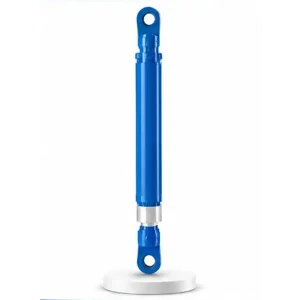
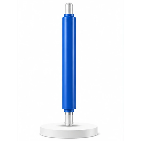
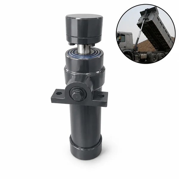
Hydraulic Press Front Side Shift Cylinder

300 mm of Adjustment.
The Difference Between
On-Centre and Off.
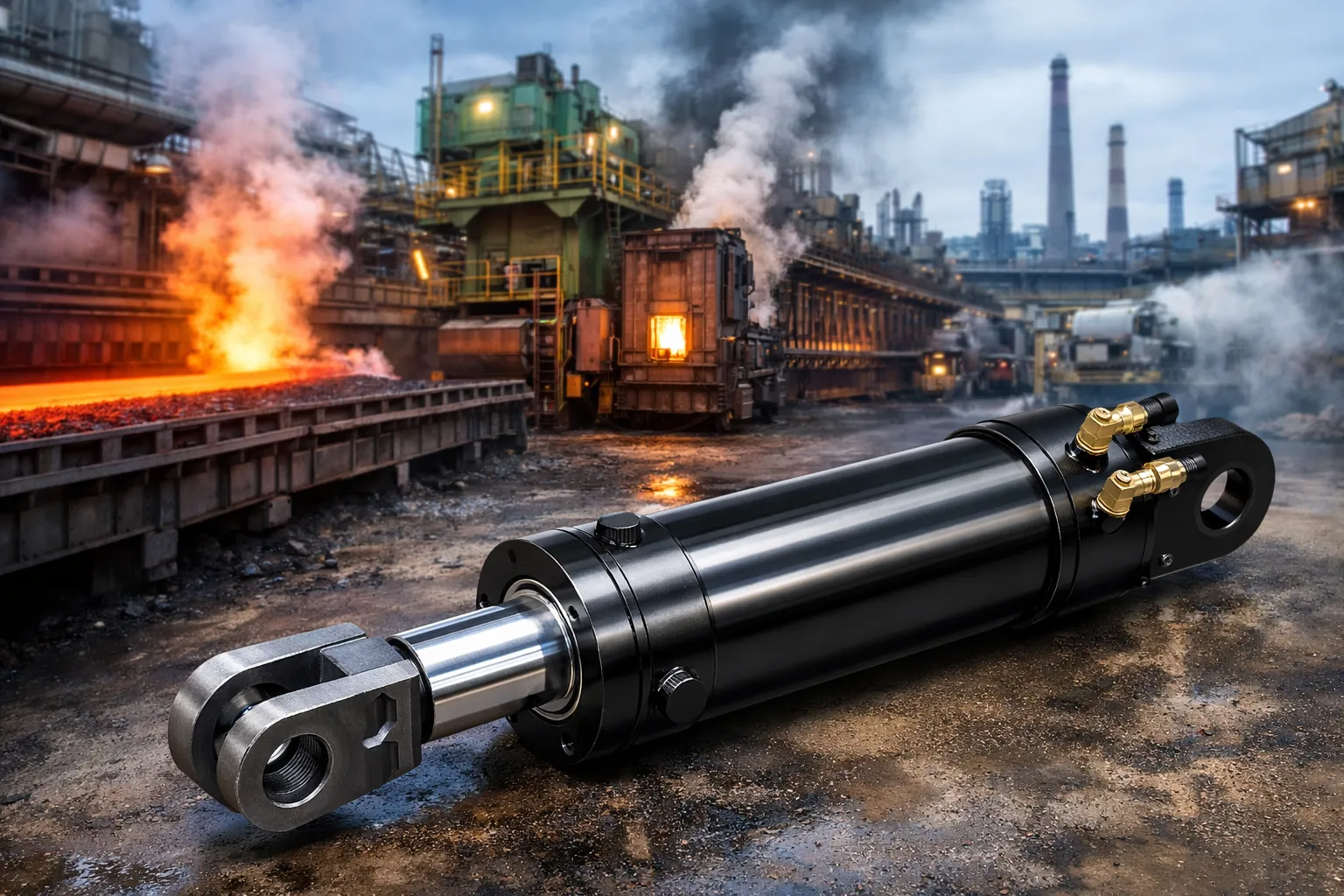
After the billet is gripped, the centering cylinder has done its job — the clamp head is centred. But the billet itself may not be perfectly centred within the jaws. The front side shift cylinder makes the final correction — nudging the gripped billet left or right by up to 300 mm so its axis aligns exactly with the die centre. This is the last adjustment before the press fires.
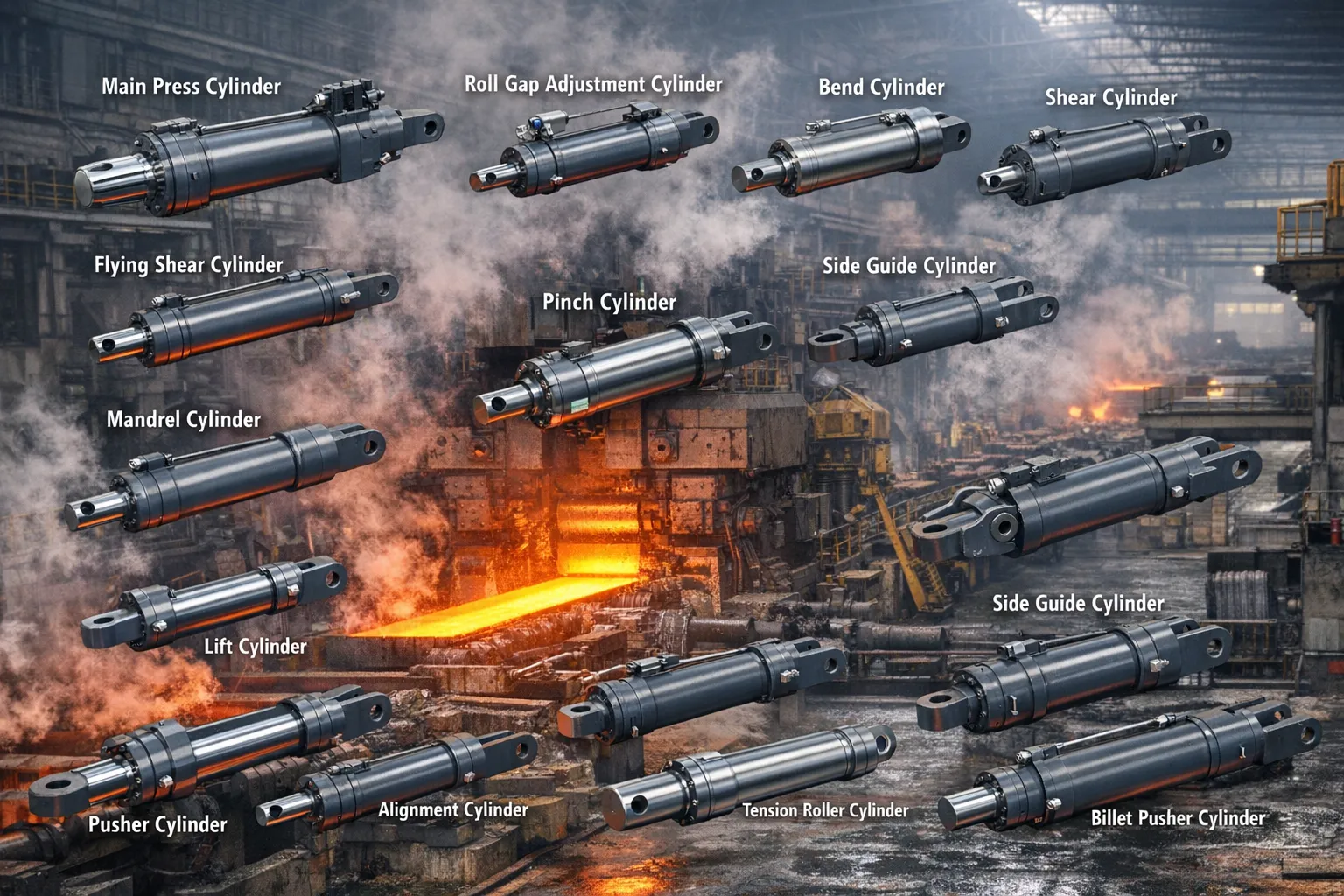
Where the Front Side Shift Fits in the Manipulator Sequence
The forging manipulator has five cylinder functions that act in sequence to position a billet correctly under the press. The front side shift cylinder is the fourth step — after centering, after clamping, and after any tilt adjustment:
The side shift is the final positioning adjustment — the last cylinder to act before the master cylinder fires. It corrects for any remaining horizontal misalignment between the billet axis and the die centre after the centering, clamping, and tilt steps have completed. Korea Ever-Power manufactures front side shift cylinders as part of the complete industrial engineering hydraulic cylinder set for manipulator builders.
Technical Specifications
| Parameter | Value |
|---|---|
| Product | Hydraulic Press Front Side Shift Cylinder |
| Function | Move the blank or workpiece horizontally (fine adjustment) |
| Type | Plunger (single-acting) |
| Plunger Diameter | 80 mm – 240 mm |
| Stroke | ≤ 300 mm |
| Maximum Thrust | 1,130 KN (plunger 240 mm / pressure 25 MPa) |
| Working Pressure | Up to 25 MPa |
| Certification | ISO 9001 · 100% hydrostatic tested |
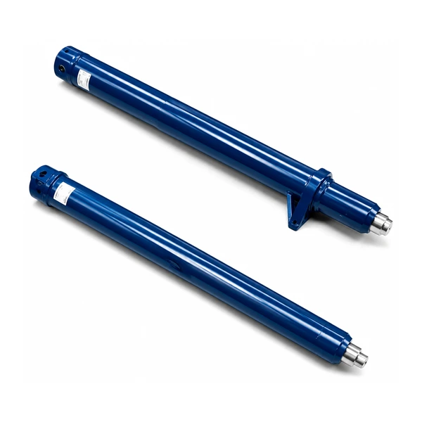
Front + Rear — Why Side Shift Needs Two Cylinders
A single push-point would rotate the billet in the clamp instead of shifting it. Two push-points — front and rear — apply parallel forces at both ends of the billet, shifting it sideways without rotation. This is the same principle as pushing a heavy box with both hands instead of one: one hand and the box pivots; both hands and it slides straight.
Both cylinders are fed from the same hydraulic circuit through a flow divider, ensuring synchronised extension speed. If one extends faster than the other, the billet rotates in the clamp — exactly the error the dual-cylinder design exists to prevent. Korea Ever-Power manufactures the front and rear side shift cylinders as a matched pair with verified synchronisation. Contact the hydraulic cylinder engineering team for paired side shift specifications.
Why Plunger Type — Compact, Simple, Ideal for Short Strokes
The front side shift cylinder uses a plunger (solid rod) rather than a piston-and-bore arrangement. Hydraulic pressure acts on the plunger's end face to extend it; retraction relies on the opposing rear side shift cylinder or gravity (depending on mounting orientation). This single-acting design is chosen for three reasons specific to the side shift application:
Compact length. A plunger cylinder with 300 mm stroke is significantly shorter than a piston cylinder with the same stroke — because there is no rod gland, no rod-side oil chamber, and no separate end cap. On a manipulator clamp where mounting space is tight, this compactness is critical.
Fewer seals. A plunger cylinder has only a plunger seal and a wiper — no piston seal, no rod seal. Fewer seals mean less friction, smoother low-speed motion (important for fine positioning), and fewer maintenance points.
Simpler hydraulics. Single-acting means only one pressure port — the return is handled by the opposing cylinder or a spring. One fewer hose, one fewer port, one fewer potential leak path in the harsh forge environment. The simplicity directly improves reliability.
Three Levels of Horizontal Positioning on a Press
The hydraulic press system has three different horizontal-motion cylinders — each operating at a different scale, speed, and purpose. Understanding which one handles which adjustment prevents specification errors.
Travel: ≤7,500 mm · Moves entire workbench in/out of press frame · Setup-level movement between production runs.
Travel: ≤5,500 mm · Moves anvil between die stations inside the frame · Production-level shifting between forging steps.
Travel: ≤300 mm · Fine-adjusts billet position within the clamp · Stroke-level correction before each press hit.
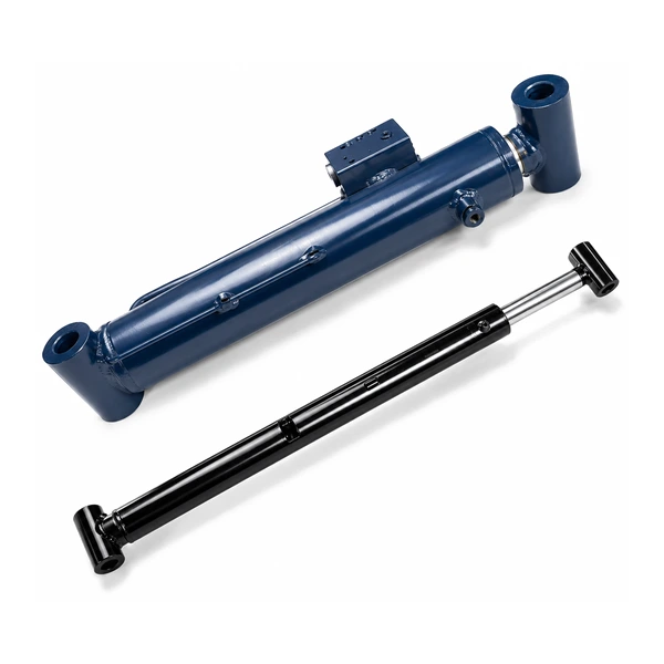
Manufacturing — Matched Pairs for Synchronised Shifting
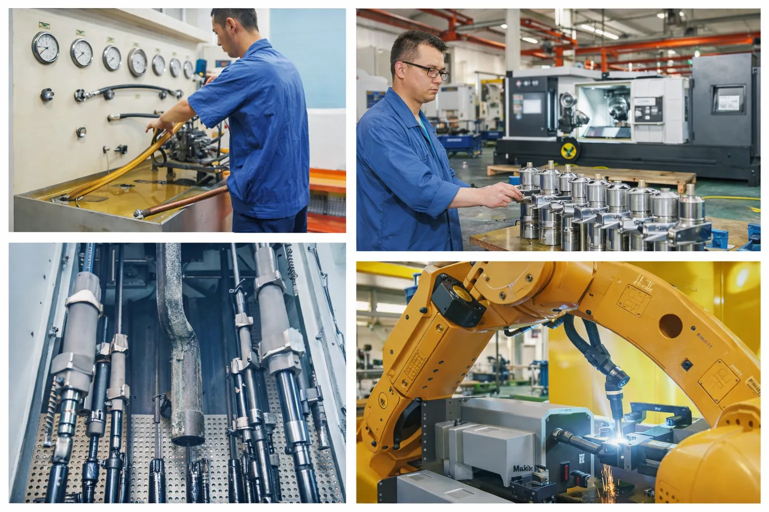
The front and rear side shift cylinders are manufactured as a matched pair. "Matched" means the plunger diameters are held to mutual tolerance so that at the same hydraulic flow, both cylinders extend at the same speed — preventing billet rotation during the shift. The plunger surface finish (chrome plated, ground to Ra ≤0.4 µm) and seal specification are identical between front and rear cylinders.
Because the front side shift cylinder is mounted on the manipulator in the forge environment, it receives the same environmental protection as the tilt and clamping cylinders: high-temperature seals, heavy-duty wipers, and chrome plating thickness appropriate for scale and forge-spray exposure. The plunger type's simpler seal arrangement (only plunger seal + wiper) means fewer components exposed to the hostile environment — contributing to the reliability advantage of the plunger design in forge service.
Every side shift cylinder pair is hydrostatic tested individually, then functionally tested together — verifying matched extension speed and synchronised positioning across the full 300 mm stroke.
OEM & ODM
FAQ
Related Categories
其他信息
| Editor |
|---|