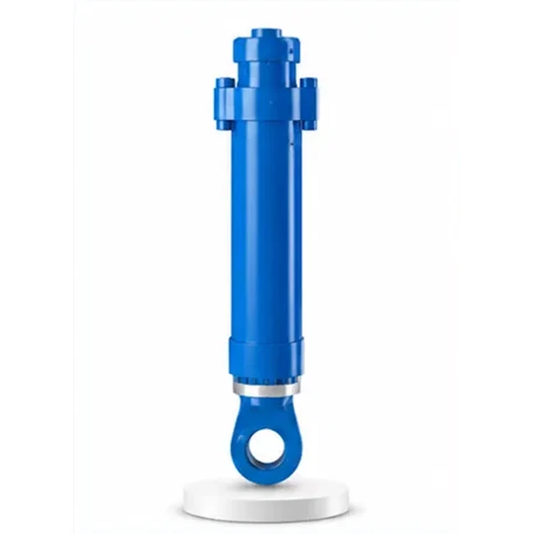
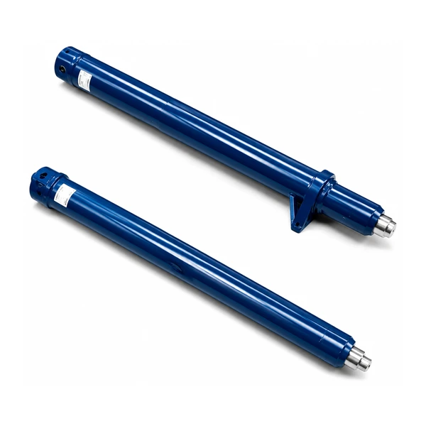
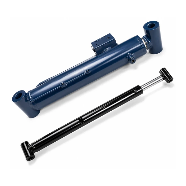
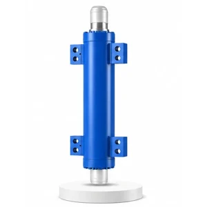
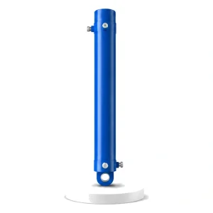
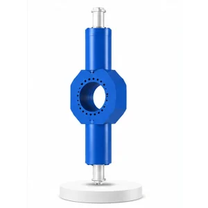
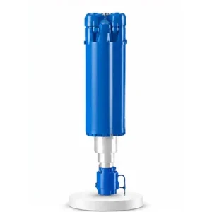
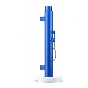
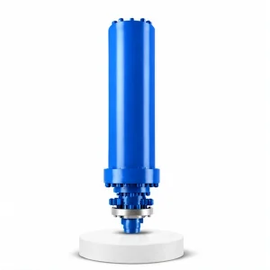
Hydraulic Press Tilt Cylinder

The Cylinder That
Turns the Workpiece
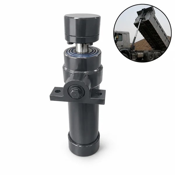
A 5-tonne steel billet at 1,200 °C must be rotated between forging passes — repositioned precisely so the next press stroke hits a different face. The operator cannot touch it. The crane cannot reach it fast enough. The tilt cylinder on the forging manipulator does it in seconds: lifting the clamp head, rotating the billet to the target angle, and holding it steady while the press fires.
What Is a Forging Manipulator — And Why It Needs a Tilt Cylinder
A forging manipulator is a heavy-duty machine that grips, lifts, translates, and rotates hot metal billets and forgings under a hydraulic press. Think of it as a giant robotic arm that holds the workpiece between the dies — positioning it for each press stroke, then repositioning it for the next. On a large free-forging press producing shafts, rings, and blocks, the manipulator handles billets weighing 1–50 tonnes at temperatures of 800–1,250 °C.
The manipulator's clamp head — the jaws that grip the billet — must be able to tilt up and down so the billet can be presented to the dies at the correct angle for each forging pass. This tilting motion is powered by the tilt cylinder. The cylinder pushes one end of the clamp head upward (or downward), pivoting it around a hinge axis — converting the cylinder's linear stroke into the angular rotation of the clamp. Korea Ever-Power manufactures tilt cylinders as part of the full industrial engineering hydraulic cylinder programme for manipulator builders and forge shops.
Technical Specifications
| Parameter | Value |
|---|---|
| Product | Hydraulic Press Tilt Cylinder |
| Function | Lifting and tilting the manipulator clamp head |
| Bore Diameter | 100 mm – 400 mm |
| Rod Diameter | 50 mm – 300 mm |
| Stroke | ≤ 1,500 mm |
| Maximum Thrust | 3,141 KN (bore 400 mm / pressure 25 MPa) |
| Working Pressure | Up to 25 MPa |
| Certification | ISO 9001 · 100% hydrostatic tested |
Linear Stroke → Angular Rotation — How the Geometry Works

The tilt cylinder is a linear actuator — it pushes and pulls in a straight line. But the clamp head needs to rotate. The conversion from linear to angular motion happens through a lever arm: the cylinder rod attaches to a point on the clamp head at a distance from the pivot axis. As the cylinder extends, it pushes that point in an arc around the pivot, tilting the entire clamp head.
The lever arm length determines the relationship between cylinder stroke and tilt angle. A longer lever arm produces more tilt angle per millimetre of cylinder stroke (greater mechanical advantage for speed) but requires more cylinder force (less mechanical advantage for force). A shorter lever arm produces less angle per stroke but multiplies the cylinder force. The manipulator designer selects the lever arm length to balance the tilt speed and the torque required to rotate the loaded clamp head.
This is why the tilt cylinder's stroke is shorter than any other press cylinder — ≤1,500 mm compared to ≤4,500 mm for the master cylinder. A 1,500 mm stroke through a typical lever arm geometry produces 60–90° of clamp head rotation, which is the full angular range most forging operations require. The cylinder does not need more stroke because the lever arm amplifies it into angular travel.
The Harshest Working Environment on Any Press Cylinder
Press cylinders — master, side, return, leveling — are mounted on or inside the press frame, which provides some shielding from the forging environment. The tilt cylinder has no such luxury. It is mounted on the manipulator arm — directly alongside the hot workpiece, exposed to:
The billet at 1,200 °C radiates intense heat directly onto the cylinder barrel and rod. Sustained exposure raises the cylinder surface temperature to 80–150 °C — well above the normal operating range for standard seals. The tilt cylinder requires high-temperature seals (FKM or equivalent) and may need heat shielding to protect the barrel paint and the hydraulic fluid from thermal degradation.
Iron oxide scale flakes off the hot billet during each press stroke, showering the manipulator and its cylinders with abrasive particles. Forge spray — a water/graphite lubricant mixture applied to the dies — splashes onto the cylinder rod, carrying scale particles that are drawn past the wiper seal. Heavy-duty wiper seals and rod boots are essential for tilt cylinder longevity in the forge environment.
Every press stroke transmits a shock wave through the workpiece, through the manipulator clamp, and into the tilt cylinder mounting. Over thousands of daily press strokes, this repeated shock loading fatigues the cylinder mounting brackets, pin joints, and the rod end connection. The tilt cylinder's mounting hardware must be designed for fatigue loading — not just static force.
Between every press stroke, the manipulator repositions the billet — which means the tilt cylinder may cycle 2–4 times per press cycle (tilt up, hold, tilt down, hold). On a press running 3 strokes per minute, the tilt cylinder cycles 6–12 times per minute — accumulating seal wear faster than any other cylinder in the press system.
Safety — When the Tilt Cylinder Holds a Hot Billet Overhead
The tilt cylinder is a safety-critical actuator. When the clamp head is tilted upward, the hot billet is elevated and cantilevered — its weight creates a moment arm that tries to rotate the clamp head back down. If the tilt cylinder loses pressure or its load-holding valve fails, the clamp head drops — swinging the billet downward in an uncontrolled arc.
Every tilt cylinder on a forging manipulator must include a pilot-operated check valve or counterbalance valve on the rod-side port. This valve locks the cylinder in position when the directional valve is in neutral — preventing gravity-driven rotation of the loaded clamp head. The valve must be mounted directly on the cylinder port (not remotely) to eliminate the risk of hose failure between the valve and the cylinder causing an uncontrolled drop.
During manipulator maintenance, a mechanical tilt lock pin must be inserted through the clamp head pivot to physically prevent rotation — the hydraulic tilt cylinder alone is never relied upon as the sole means of holding the clamp head during maintenance. Korea Ever-Power can integrate the mechanical lock pin provisions into the cylinder mounting design on request.
Korea Ever-Power designs every tilt cylinder with load-holding valve mounting provisions as standard — not as an option. The cylinder port face includes pre-drilled and tapped holes for direct valve mounting. Contact the hydraulic cylinder safety engineering team for manipulator cylinder specifications.
Manufacturing for the Forge Environment
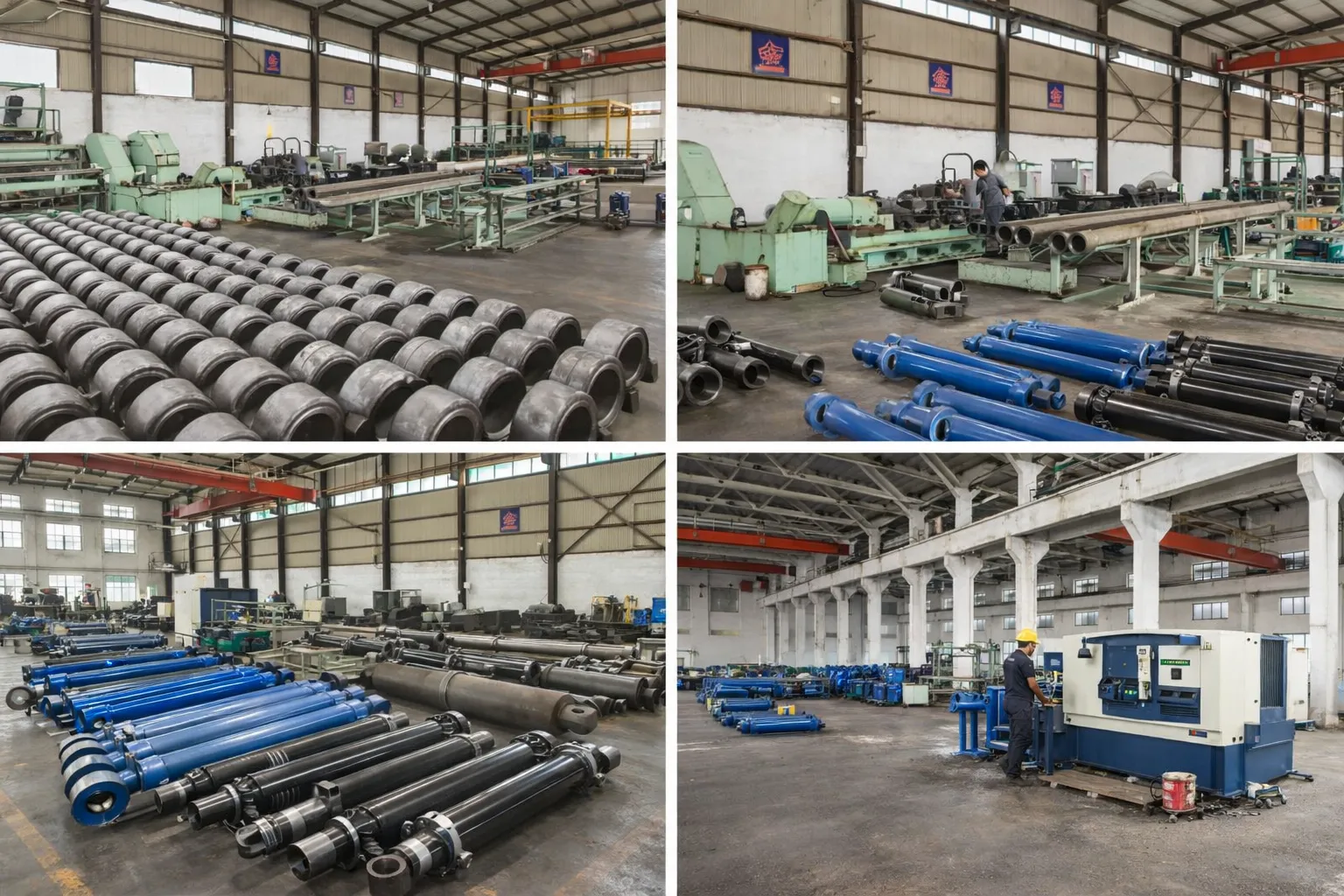
The tilt cylinder's exposure to heat, scale, and shock means it requires more robust construction than a cylinder operating inside the press frame. Korea Ever-Power builds forge-environment tilt cylinders with heavier wall thickness (additional safety margin for shock loading), high-temperature seals as standard (FKM piston seals, PU wipers with scale guards), and heavy-duty chrome plating (40–50 µm) on the rod to resist abrasion from scale particles.
The rod end connection — where the cylinder attaches to the clamp head lever arm — is the highest-stress point on the assembly. Korea Ever-Power machines this connection from a single forged block (not welded-on fabrication) to eliminate the fatigue crack initiation risk at a weld toe. The pin bore is induction-hardened for wear resistance under the oscillating pin loading.
Every tilt cylinder is hydrostatic tested at 1.5× working pressure. For manipulator applications, the cylinder is also functionally tested for full-stroke extension and retraction speed to verify consistent motion quality — no stick-slip, no hesitation — which is critical for smooth, predictable clamp head tilting during live forging operations.
OEM & ODM
FAQ
Related Categories
其他信息
| Editor |
|---|
相关产品
-
Pressurized Hydraulic Cylinder for Vulcanizing Machine
-
Electric Furnace Tipping Cylinder
-
Hydraulic Press Centering Cylinder
-
Cement Equipment Roll over Cylinder
-
Hydraulic Press Rear Side Shift Cylinder
-
Hydraulic Press Clamping Cylinder
-
Electric Furnace Lifting Cylinder
-
Hydraulic Press Master Cylinder


