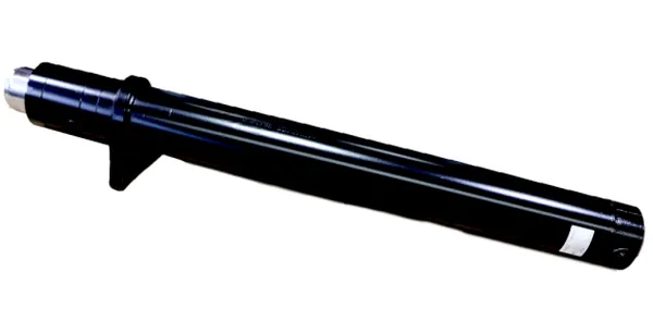
Forklift Short Lifting Hydraulic Cylinder — Free-Lift Cylinder with Integrated Check Valve and Sprocket System

What Is Free Lift — And Why It Needs a Dedicated Cylinder
Free lift is fork travel that occurs without any increase in the overall mast height. On a two-stage (simplex) mast, every millimetre of fork rise extends the mast by approximately the same amount — there is no free lift at all. On a three-stage (triplex) mast with a short lifting cylinder, the forks can rise through the full free-lift stroke before the mast begins to extend. This free-lift capability is what allows the forklift to raise loads inside height-restricted environments — shipping containers, low-ceiling warehouses, between-deck vehicle transport holds, and freezer tunnels.
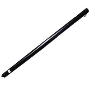
The short lifting cylinder achieves this by operating independently of the main lifting cylinder during the first phase of the lift stroke. Hydraulic oil flows first to the short cylinder (controlled by a sequencing valve or a flow divider), extending it through its 775–800 mm stroke. During this phase, the chain wrapped around the sprocket on top of the cylinder translates the piston rod extension into carriage movement — typically at a 2:1 ratio (for every 1 mm of rod extension, the carriage rises 2 mm). Once the short cylinder reaches full extension, the sequencing valve redirects flow to the main lifting cylinder, and the mast begins extending in the normal manner.
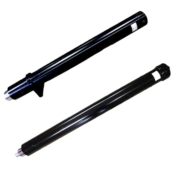
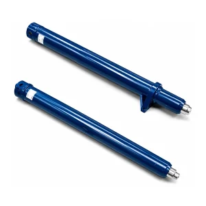
Unlike the main lift cylinder (which connects to the mast chain at a separate anchor point), the short lifting cylinder has a built-in sprocket seat and sprocket cover at the top of the piston rod. The lift chain wraps over this sprocket, converting the linear rod extension into carriage lift. This integrated design eliminates the external sheave bracket that would otherwise be needed, reducing the parts count and the potential failure points in the free-lift system.
Dimensional Specifications — 5 Short Lift Cylinder Models
Five models in two mounting configurations cover triplex mast forklifts from 2.5 to 5 tonnes. All models share the same M22×1.5 metric hydraulic port and 18.1 MPa working pressure. The bore-to-rod area ratio across all models is notably lower than standard lift cylinders — producing higher annular area for improved load-holding stability during free lift.
Configuration A — 800 mm Stroke, 1,065 mm Installation Distance

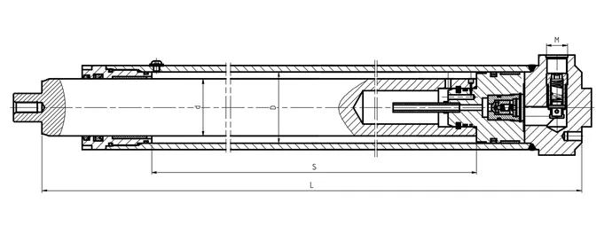
| Drawing Number | Bore (D) | Rod (d) | Stroke (S) | Install Dist (L) | Pressure | Ports (M) | Weight |
|---|---|---|---|---|---|---|---|
| RC25N480-800000-000A | Φ75 | Φ60 | 800 | 1065 | 18.1 MPa | M22×1.5 | 36 kg |
| X35N480-800000-001A | Φ95 | Φ80 | 800 | 1065 | 18.1 MPa | M22×1.5 | 48.7 kg |
Configuration B — 775–777 mm Stroke, 1,013–1,015 mm Installation Distance
| Drawing Number | Bore (D) | Rod (d) | Stroke (S) | Install Dist (L) | Pressure | Ports (M) | Weight |
|---|---|---|---|---|---|---|---|
| N30N450-800000-002A | Φ85 | Φ70 | 777 | 1015 | 18.1 MPa | M22×1.5 | 45.5 kg |
| 3U3H-800000-001A | Φ85 | Φ70 | 777 | 1015 | 18.1 MPa | M22×1.5 | 45.5 kg |
| N35N450-800000-003A | Φ95 | Φ80 | 775 | 1013 | 18.1 MPa | M22×1.5 | 54 kg |
Models N30N450 and 3U3H share identical bore, rod, stroke, and installation dimensions but have different mounting bracket configurations for different forklift OEM platforms. Always cross-reference by the complete drawing number, not by bore/stroke alone. All ports M22×1.5 metric.
Integrated Check Valve — The Load-Holding Safety System
Unlike the main lift cylinder (which relies on an external check valve in the hydraulic circuit), the short lifting cylinder integrates the check valve directly into the cylinder body. This design eliminates the external hose run between the cylinder port and a remote check valve — removing a potential leak point and a potential failure point from the free-lift safety chain.
The check valve allows oil to flow freely into the cylinder (lift direction) but blocks oil from flowing out (lower direction) unless the flow path is opened by the directional control valve. If a hose upstream of the cylinder fails while the forks are raised in the free-lift zone, the check valve traps the oil inside the cylinder and the forks hold position. The load cannot descend until the operator deliberately activates the lowering control.
During free lift, the forklift is typically inside a confined space — a shipping container, a vehicle hold, or a low-ceiling area. An uncontrolled fork descent in these environments is more dangerous than in open warehouse space because the operator has limited escape routes and the load may strike the container ceiling or doorframe on the way down. The integrated check valve provides immediate, zero-delay load holding with no reliance on external components.
The oil pipe built into the cylinder assembly routes hydraulic fluid from the check valve through an internal passage to the cylinder bore port. This internal routing eliminates the external pipe or hose that would otherwise run along the exposed outer surface of the cylinder — where it would be vulnerable to damage from chain contact, mast channel friction, and debris impact during container loading operations.
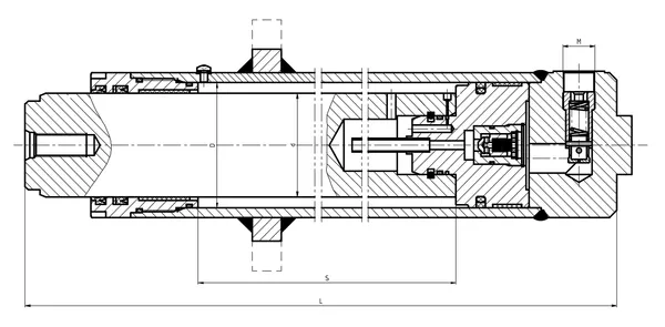
27-Component Assembly — Including Sprocket and Valve Systems
The short lifting cylinder is the most complex single cylinder in the forklift hydraulic system — 27 components versus 25 for the tilt cylinder and 16 for the steering cylinder. The additional complexity comes from three subsystems that other forklift hydraulic cylinders do not include: the check valve assembly (item 4), the oil pipe (item 3), and the sprocket seat/cover pair (items 11–12).
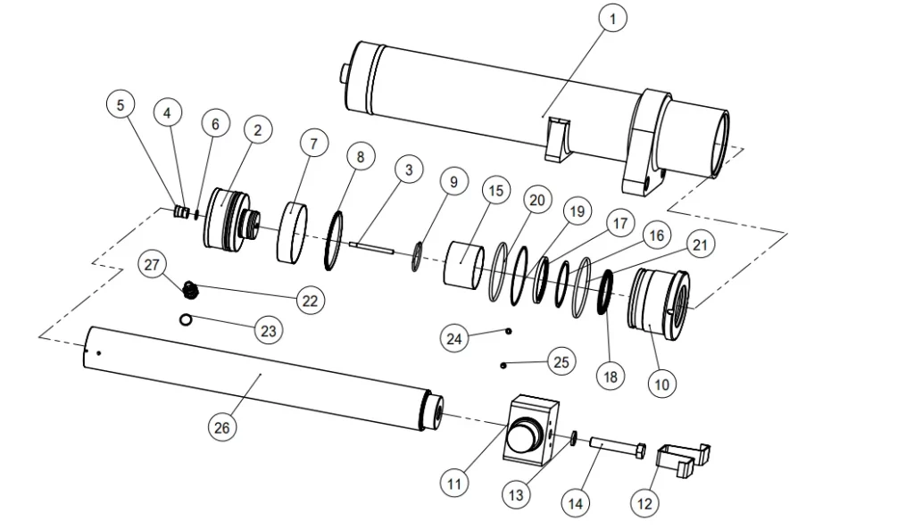
| # | Component | # | Component | # | Component |
|---|---|---|---|---|---|
| 1 | Cylinder Housing Assy | 10 | Guide Bush | 19 | Back-Ring |
| 2 | Piston | 11 | Sprocket Seat ◆ | 20 | O-Ring |
| 3 | Oil Pipe ◆ | 12 | Sprocket Cover ◆ | 21 | O-Ring |
| 4 | Check Valve ◆ | 13 | Spring Washers | 22 | Grease Nipple |
| 5 | Circlips for Hole | 14 | Hex Bolt | 23 | O-Ring |
| 6 | O-Ring | 15 | Du Bush | 24 | Washer |
| 7 | Wear-Ring | 16 | Back-Ring | 25 | Screws |
| 8 | Hole Seal | 17 | Rod Seal | 26 | Piston Rod |
| 9 | Round Wire | 18 | Dust Wiper | 27 | Plug |
◆ Components unique to the short lifting cylinder — not found in standard lift, tilt, or steering cylinders.
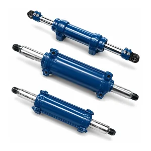
Short Lift Cylinder vs Main Lift Cylinder — Technical Comparison
Buyers occasionally confuse the short lift cylinder with the main lift cylinder. They are entirely different components, are not interchangeable, and perform different functions within the mast system. This comparison clarifies the distinctions.
| Characteristic | Short Lift Cylinder | Main Lift Cylinder |
|---|---|---|
| Function | Free lift only (no mast extension) | Full mast extension |
| Stroke | 775–800 mm | 1,500 mm |
| Bore Range | Φ75–Φ95 (larger) | Φ56–Φ60 (smaller) |
| Rod Diameter | Φ60–Φ80 (thicker) | Φ45 |
| Integrated Check Valve | Yes | No (external) |
| Sprocket System | Integrated (seat + cover) | External chain anchor |
| Mounting Position | Centre of inner mast channel | Side of mast frame |
| Component Count | 27 parts | ~20 parts |
Why Short Lift Cylinders Use Thicker Piston Rods
The rod-to-bore diameter ratio on the short lift cylinder (approximately 0.80–0.84) is substantially higher than the main lift cylinder (approximately 0.75–0.80). This thick rod design serves two engineering purposes that are unique to the free-lift function.
First, the thick rod provides column stability. The short lift cylinder mounts vertically in the centre of the mast channel with no lateral support along the rod's extended length. At 800 mm extension, the unsupported rod length creates a column buckling risk under the full lift load. A thicker rod (Φ60–Φ80 versus Φ45 on the main lift cylinder) increases the rod's moment of inertia — its resistance to lateral bending — by the fourth power of the diameter increase. Going from Φ45 to Φ60 increases column strength by a factor of (60/45)⁴ = 3.16.
Second, the thick rod provides a mounting platform. The sprocket seat (item 11) bolts to the top of the piston rod. The rod must be thick enough to accommodate the bolt holes, the sprocket bearing, and the chain load reaction forces without concentrating stress around the bolt holes. A thinner rod would require a separate adapter plate between the rod and the sprocket — adding weight, adding a potential failure point, and increasing the overall cylinder height.
Where Free Lift Is Essential — Not Optional

Container Stuffing and Destuffing
The primary application for free-lift masts. The forklift drives into 20-foot or 40-foot shipping containers (2,280 mm internal clearance at the door) and must raise pallets to stack two-high inside the container without the mast contacting the container ceiling. Free lift provides the 800+ mm of fork travel needed to achieve this double-stack height while keeping the mast below the door header during entry and exit.
Low-Ceiling Warehouses and Mezzanines
Older warehouse buildings and mezzanine areas with ceiling clearances below 2,500 mm cannot accommodate a standard extending mast. The free-lift cylinder allows the forklift to operate in these areas, raising loads up to the first racking level without the mast top hitting structural beams, sprinkler piping, or ceiling panels. This extends the useful life of older warehouse buildings without requiring costly ceiling height modifications.
Vehicle Transport — RoRo and Car Carrier
Forklifts loading cargo between decks of RoRo vessels and multi-deck car carriers face inter-deck clearances as low as 2,200 mm. The free-lift cylinder enables these forklifts to raise and place cargo on the between-deck shelving systems without extending the mast into the overhead deck structure. The short lift cylinder's integrated check valve provides the load security required during vessel operations where deck motion and vibration could otherwise cause load shift.
Short Lifting Cylinder — Frequently Asked Questions
Complete Mast Cylinder Set
Additional information
| Editor | Cxm |
|---|
Related products
-
Forklift Tilt Cylinder | EP-HCYY11112001 Model
-
Forklift Truck Lift Oil Cylinder — Single-Acting Hydraulic Lift Cylinder
-
20176B-02000 Forklift Truck Support Hydraulic Cylinder
-
Industrial Vehicle Short Stroke Forklift Lift Cylinder
-
Custom Hydraulic Cylinder for Forklift Steering
-
Forklift Steering Hydraulic Cylinder — Double-Acting Dual-Rod Power Steering Cylinder for 2–10 Ton Forklifts
-
Forklift Lifting Hydraulic Cylinder — Single-Acting Mast Lift Cylinder
-
Forklift Lifting Hydraulic Cylinder


